
Lithographic apparatus and device manufacturing method

a technology of lithographic apparatus and manufacturing method, which is applied in the direction of optical devices, instruments, photomechanical apparatus, etc., can solve the problems of real risk of debris, glass or other materials, particles present on the substrate, and difficult to clean all such contaminants from the substrate, so as to reduce the risk of damage to and contamination of the lens array

Inactive Publication Date: 2007-01-02
ASML NETHERLANDS BV
View PDF26 Cites 31 Cited by
  • Summary
  • Abstract
  • Description
  • Claims
  • Application Information

AI Technical Summary

Benefits of technology

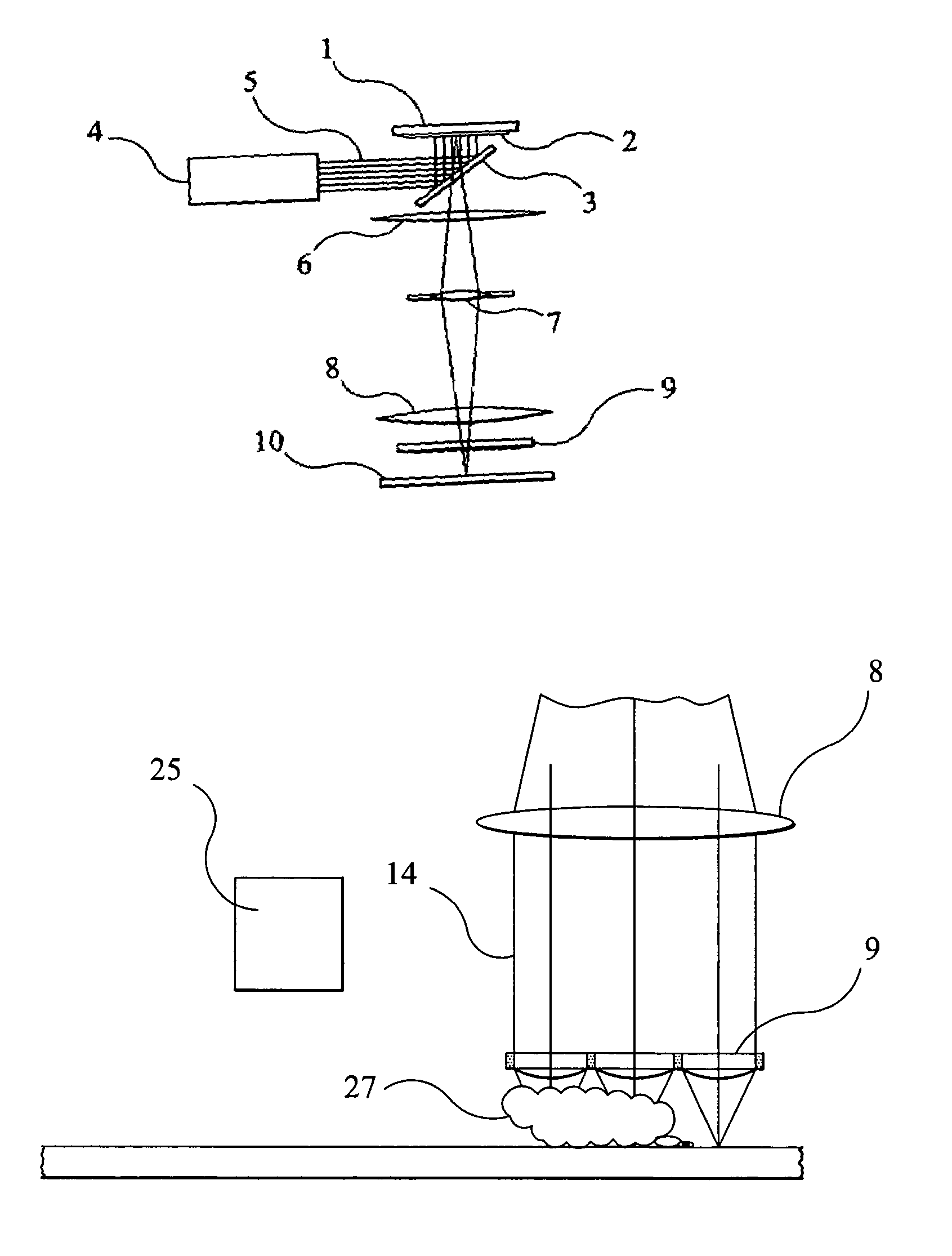
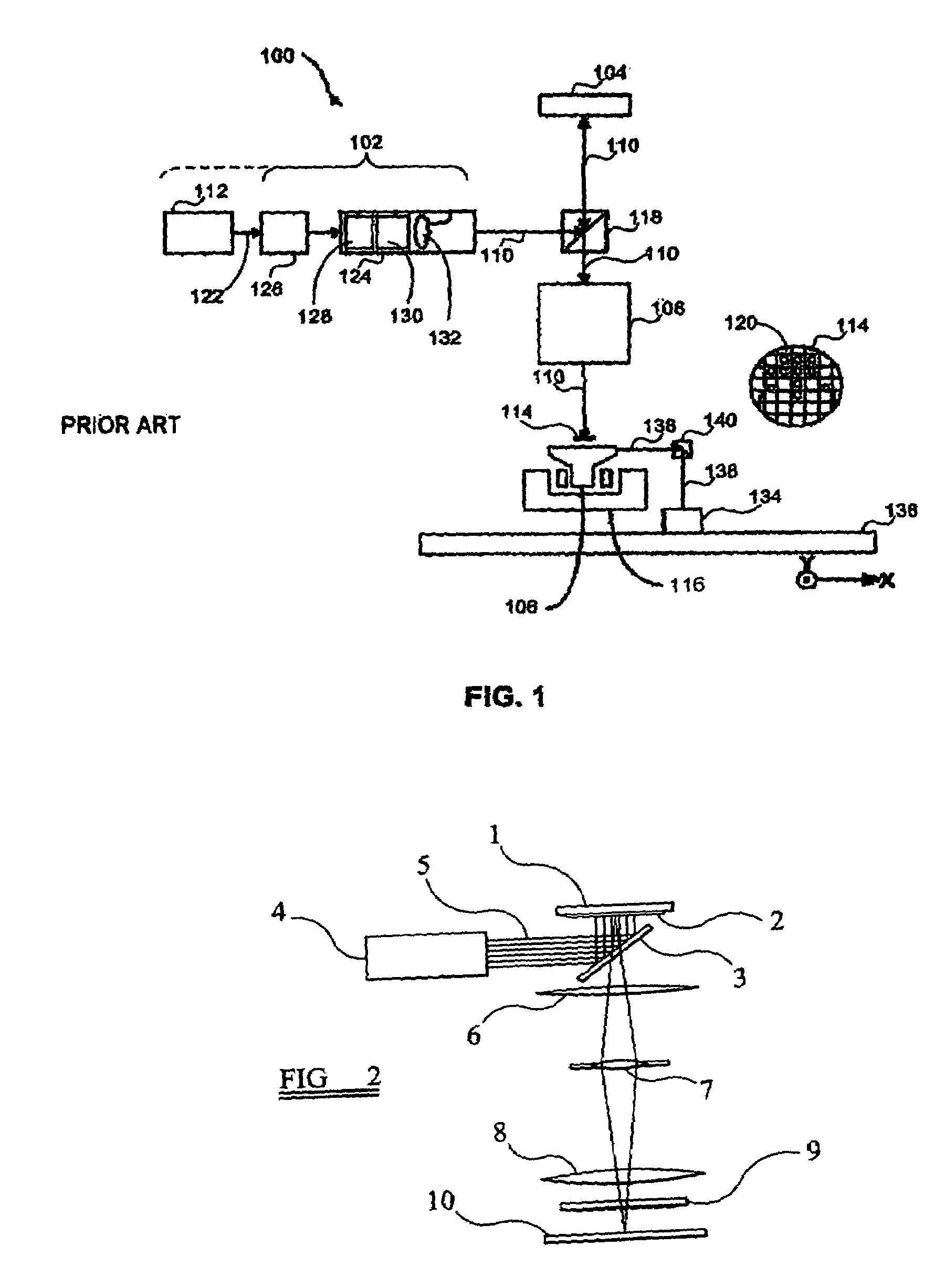
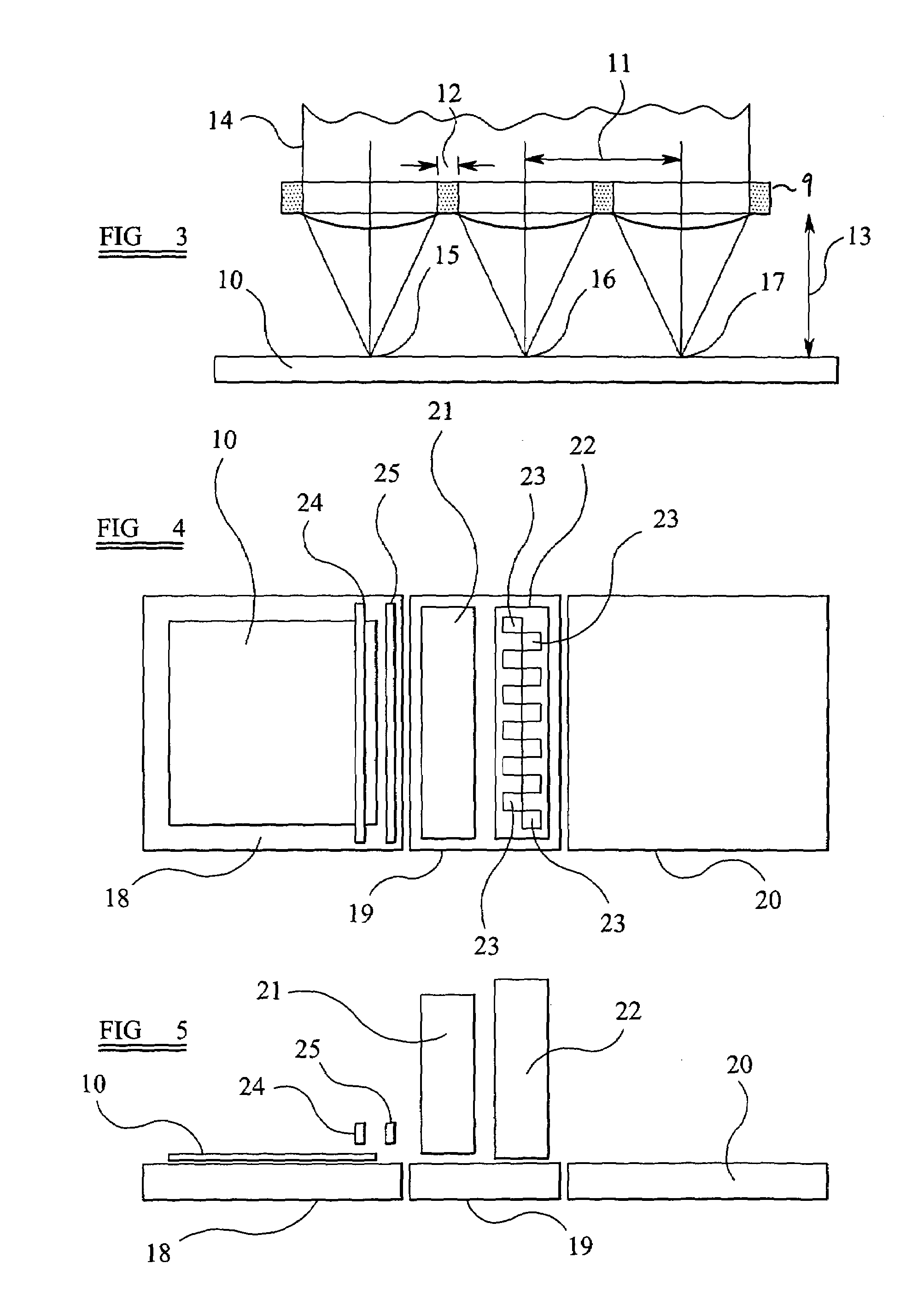
The present invention provides a lithographic apparatus and method that can detect and avoid particles on a substrate during the patterning process. By raising the lens array out of harm's way when a particle is detected, damage to the lens array can be avoided. The lens array can be part of an optical engine that is displaced as a unit to increase the array / substrate spacing, or only the lens array of the optical engine may be displaced. A pellicle can be used to reduce the risk of damage to and contamination of the lens array. A cleaning device can be used upstream of the detector to clear displaceable particles off the substrate. The patterned beam can be produced using a mask or reticle, or using an array of individually controllable elements.

Problems solved by technology

With such large thin panels there is a real risk of debris, for example particles of glass or other materials, being present on the substrate.
For instance, if the substrate has been coated with a resist prior to its exposure in the lithographic apparatus, it can be difficult to clean all such contaminants from the substrate.
If a particle that is larger than the free working distance between the substrate and the lens array is present on the substrate, it will contact the lens array as the substrate is advanced beneath the lens array, and as a result, will cause damage to the substrate, leading generally to the rejection of the damaged substrate.
Of greater significance is that such a particle collision may well scratch or cause other damage to the lenses of the array.
Such an event would necessitate replacement of the lens array, which is a time consuming and expensive maintenance issue.

Method used


Image

  • Lithographic apparatus and device manufacturing method
  • Lithographic apparatus and device manufacturing method
  • Lithographic apparatus and device manufacturing method

Examples


Embodiment Construction

Overview and Terminology

[0032]Although specific reference may be made in this text to the use of lithographic apparatus in the manufacture of integrated circuits (ICs), it should be understood that the lithographic apparatus described herein may have other applications, such as the manufacture of integrated optical systems, guidance and detection patterns for magnetic domain memories, flat panel displays, thin-film magnetic heads, etc. The skilled artisan will appreciate that, in the context of such alternative applications, any use of the terms “wafer” or “die” herein may be considered as synonymous with the more general terms “substrate” or “target portion,” respectively. The substrate referred to herein maybe processed, before or after exposure, in for example a track (e.g., a tool that typically applies a layer of resist to a substrate and develops the exposed resist) or a metrology or inspection tool. Where applicable, the disclosure herein may be applied to such and other subs...


PUM


Abstract

A lithographic apparatus and method in which an illumination system supplies a projection beam, a patterning system imparts to the beam a pattern in its cross section, and a projection system projects the patterned beam onto a target portion of a substrate. The projection system comprises an array of lenses spaced from the substrate such that each lens in the array focuses part of the patterned beam onto the substrate. A displacement system causes displacement between the lens array and the substrate. A particle detector detects particles on the substrate which are approaching the lens array. A free working distance control system increases the spacing between the lens array and the substrate in response to detection of a particle. The lens array is moved away from the substrate as the detected particle passes the lens array. Thus damage to the lens array can be avoided.

Description

BACKGROUND OF THE INVENTION[0001]1. Field of the Invention[0002]The present invention relates to a lithographic apparatus and a device manufacturing method.[0003]2. Related Art[0004]A lithographic apparatus is a machine that applies a desired pattern onto a target portion of a substrate. The lithographic apparatus can be used, for example, in the manufacture of integrated circuits (ICs), flat panel displays, and other devices involving fine structures. In a conventional lithographic apparatus, a patterning means, which is alternatively referred to as a mask or a reticle, may be used to generate a circuit pattern corresponding to an individual layer of the IC (or other device), and this pattern can be imaged onto a target portion (e.g., comprising part of one or several dies) on a substrate (e.g., a silicon wafer or glass plate) that has a layer of radiation-sensitive material (e.g., resist). Instead of a mask, the patterning means may comprise an array of individually controllable e...

Claims


Application Information

Patent Timeline
Patent Type & Authority Patents(United States)
IPC IPC(8): G03B27/42G03B27/52
CPCG03F7/70275G03F7/70983G03F7/70916G03F7/70291G03F7/70925
Inventor DE JAGER, PIETER WILLEM HERMANGUI, CHENG-QUNSPIT, PETERHOEBERICHTS, EDUARD
Owner ASML NETHERLANDS BV
Learn More