Suspension apparatus for auto-focus lens device and a method for fabricating the same

a technology of suspension apparatus and lens device, which is applied in the direction of printers, cameras, instruments, etc., can solve the problems of time-consuming assembly, bulkiness and high cost, occupying considerable space, and consuming a large amount of power, so as to reduce assembly inaccuracy, reduce cost, and simplify assembly process

Inactive Publication Date: 2007-01-02
POWERGATE OPTICAL INC
View PDF1 Cites 25 Cited by
  • Summary
  • Abstract
  • Description
  • Claims
  • Application Information

AI Technical Summary

Benefits of technology

[0008]The primary object of the present invention is to provide a suspension apparatus for auto-focus lens device and a method for fabricating the same, characterized in which a lens holder and a supporting base are formed respectively at either end of a suspension spring in one piece by means of plastic injection molding, which offers the advantages of simplified assembly process and cost reduction.
[0009]Another object of the present invention is to provide a suspension apparatus for auto-focus lens device and a method for fabricating the same, which can effectively reduce assembly inaccuracy because of the high precision furnished by plastic moulds.
[0010]A further object of the present invention is to provide a suspension apparatus for auto-focus lens device and a method for fabricating the same, whereby one-piece molding is employed to allow the suspension spring in the apparatus to provide the functions of cushioning and repositioning for the two-way movements of lens holder and to greatly cut down structures required to connect various components so as to effectively reduce the volume of the whole apparatus.
[0011]Yet another object of the present invention is to provide a suspension apparatus for auto-focus lens device and a method for fabricating the same, wherein a flat-surface, circuitous and extending connecting member is designed in a suspension spring to provide a cushioning elasticity and greatly reduce the space needed.
[0012]To attain the aforesaid objects, in a preferred embodiment of the invention, the suspension apparatus for auto-focus lens device and a method for fabricating the same comprises a lens holder, a suspension spring and a supporting base. The supporting base is formed with an opening for accommodating a lens unit. The suspension spring is manufactured by stamping process to form a long strip with a plurality of suspension springs. The strip is then guided into a mold, and plastic injection molding process is performed in that mold, so as to produce the lens holder and supporting base affixed respectively to either end of the suspension spring in one piece. After that, excess material of the strip is cut off. The suspension apparatus as above described is suitable for mass production. In addition, because of the high precision of mold, the inaccuracy of assembly and fabrication is minimized. The volume of the whole apparatus and the cost of production are also vastly decreased.

Problems solved by technology

Such design has the deficiencies of complicated mechanical configuration, time-consuming assembly, bulkiness and high cost.
Most seriously, it consumes a large amount of power.
In the conventional lens unit structure just described, the spring 34 used is bulky, hence taking considerable space.
The whole assembly process is not only tedious and time consuming, the unavoidable inaccuracy in assembly also adds to the burden of quality control operation.

Method used


Image

  • Suspension apparatus for auto-focus lens device and a method for fabricating the same
  • Suspension apparatus for auto-focus lens device and a method for fabricating the same
  • Suspension apparatus for auto-focus lens device and a method for fabricating the same

Examples


Embodiment Construction

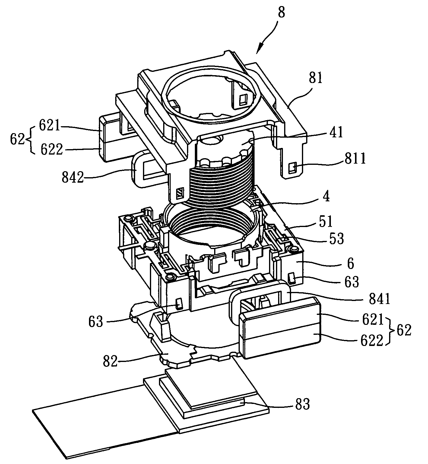
[0022]FIGS. 4, 5 and 6 show a preferred embodiment of the suspension apparatus for auto-focus lens device and a method for fabricating the same according to the present invention. FIG. 4 is a schematic diagram of a suspension spring in the suspension apparatus for auto-focus lens device; FIG. 5 is an external view of the long strip in the suspension apparatus for auto-focus lens device formed in the injection molding process; FIG. 6 is an external view of the suspension apparatus for auto-focus lens device with suspension spring and supporting base attached thereto in one piece and excess material cut off.

[0023]As shown in FIG. 4 and FIG. 5, the suspension apparatus for auto-focus lens device in this embodiment comprises a lens holder 4, a suspension spring 5 and a supporting base 6. The supporting base 6 is formed with an opening 61 (please refer to FIG. 6) for accommodating the lens holder 4. The lens holder 4 is for positioning a lens unit (not shown in the figure). The suspensio...


PUM

PropertyMeasurementUnit
lengthaaaaaaaaaa
elasticityaaaaaaaaaa
metallicaaaaaaaaaa

Abstract

A suspension apparatus comprises a lens holder, a suspension spring and a supporting base. The supporting base is formed with an opening for accommodating the lens holder. The lens holder is for positioning a lens unit. The suspension spring is manufactured by stamping process to form a long strip with a plurality of suspension springs. The strip is then guided into a mold, and plastic injection molding process is performed in that mold so as to produce the lens holder and supporting base affixed respectively to either end of the suspension spring in one piece. After that, excess material of the strip is cut off. The suspension apparatus as above described is suitable for mass production. In addition, because of the high precision of mold, the inaccuracy of assembly and fabrication is minimized. The volume of the whole apparatus and the cost of production are also vastly decreased.

Description

BACKGROUND OF INVENTION[0001]1. Field of the Invention[0002]The present invention relates to a suspension apparatus for auto-focus lens device and a method for fabricating the same, more particularly an apparatus used in camera which provides the functions of suspension and support by forming a lens holder and a supporting base respectively at either end of a suspension spring in one piece by means of plastic injection molding.[0003]2. Description of the Prior Art[0004]A standard camera 1 comprises a lens set 11, a sensor 12 and a focusing mechanism (not shown in the figure). The lens set 11 forms an image on sensor 12 by refracting the light rays from an object (as shown in FIG. 1). If the distance between lens set 11 and sensor 12 (back focal length, BFL) is fixed, the lens can only show clearly objects at a specific distance (e.g. the hyperfocal distance of 2–3 meters away). For the camera to shoot objects at a close distance, the distance between lens set 11 and sensor 12 must b...

Claims


Application Information

Patent Timeline
Patent Type & Authority Patents(United States)
IPC IPC(8): G02B15/14
CPCG02B7/023G03B3/10G02B7/026
Inventor CHANG, CHI LONEHSU, WEN TSAI
Owner POWERGATE OPTICAL INC
Why Eureka
Try Eureka