Check patentability & draft patents in minutes with Patsnap Eureka AI!

Method and apparatus for monitoring subscriber loop interface circuitry power dissipation

Inactive Publication Date: 2007-01-02
SILICON LAB INC
View PDF22 Cites 76 Cited by
  • Summary
  • Abstract
  • Description
  • Claims
  • Application Information

AI Technical Summary

Benefits of technology

[0010]Another feature is that sensing of the tip and ring lines for subscriber loop control can be accomplished across components including tip or ring inline protective devices such as fuses such that one lead of a pair of sense leads is unprotected by the fuse and the other lead is protected by the fuse. This enables using the same sensing circuitry for power monitoring as well as to determine other line conditions such as whether the fuses are blown without the use of separate sensing circuitry dedicated to that purpose. This approach reduces the number of pins on an integrated circuit needed to monitor power dissipation and determine pre-fuse line conditions.

Problems solved by technology

The interface requirements of an SLIC typically result in the need to provide relatively high voltages and currents for control signaling with respect to the subscriber equipment on the subscriber loop.
Disadvantages of this design include the bulkiness, weight, and power consumption of the passive inductive components.
One disadvantage of this design is that programming of various SLIC operational characteristics is typically accomplished using discrete components such that the SLIC operational characteristics are not dynamically modifiable.
In addition, the integrated circuit handling the higher powered analog control signaling functions tends to be relatively expensive.

Method used


Image

  • Method and apparatus for monitoring subscriber loop interface circuitry power dissipation
  • Method and apparatus for monitoring subscriber loop interface circuitry power dissipation
  • Method and apparatus for monitoring subscriber loop interface circuitry power dissipation

Examples


Embodiment Construction

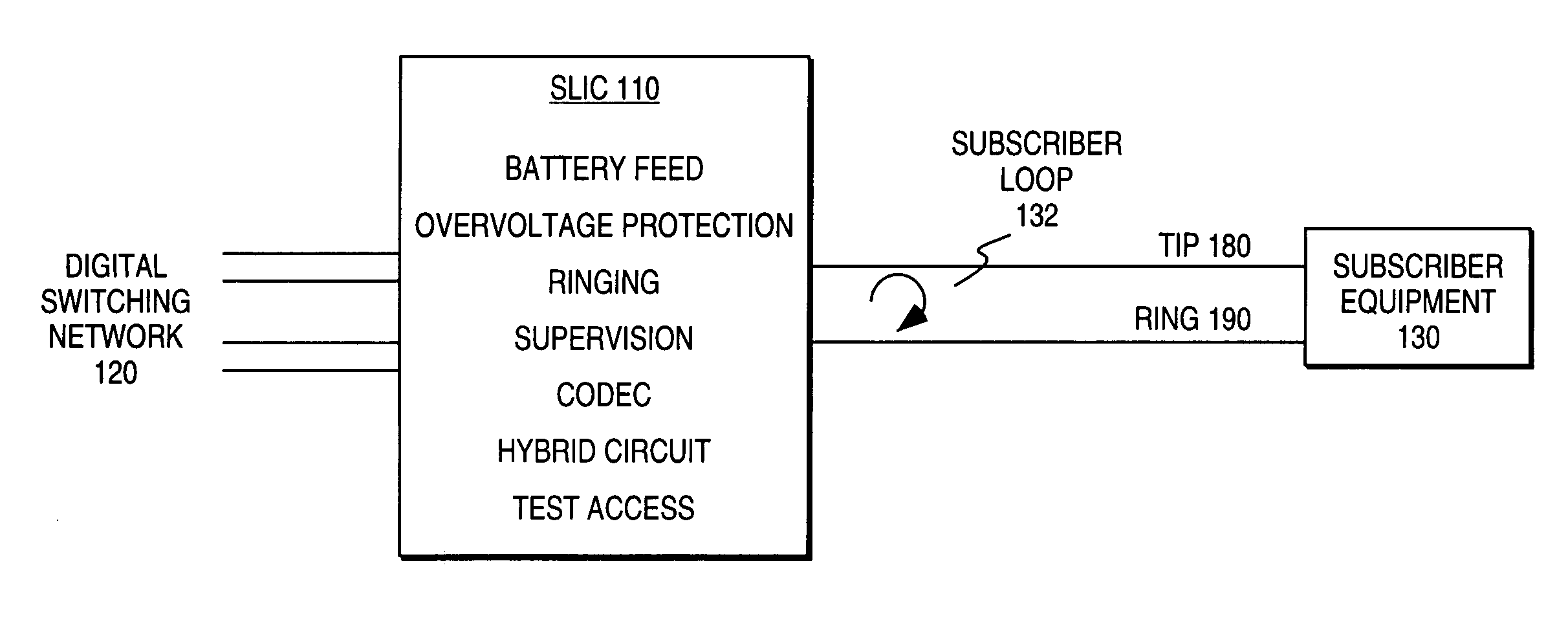
[0020]FIG. 1 illustrates functional elements of one embodiment of a subscriber line interface circuit (SLIC) 110 typically associated with plain old telephone services (POTS) telephone lines. The subscriber line interface circuit (SLIC) provides an interface between a digital switching network 120 of a local telephone company central exchange and a subscriber loop 132 including subscriber equipment 130.

[0021]The subscriber loop 132 is typically used for communicating analog data signals (e.g., voiceband communications) as well as subscriber loop “handshaking” or control signals. The analog data signals are typically on the order of 1 volt peak-to-peak (i.e., “small signal”). The subscriber loop control signals typically consist of a 48 V d.c. offset and an a.c. signal of 40–140 Vrms (i.e., “large signal”). The subscriber loop state is often specified in terms of the tip 180 and ring 190 portions of the subscriber loop.

[0022]The SLIC is expected to perform a number of functions often...


PUM


Abstract

Subscriber line interface circuitry includes an integrated circuit having sense inputs for a sensed tip signal and a sensed ring signal of a subscriber loop. The integrated circuit generates a subscriber loop linefeed driver control signal in response to the sensed signals. The linefeed driver does not reside with the integrated circuit. A method for monitoring power dissipation of the linefeed driver components includes the step of sampling at least one of the tip and ring signals to determine a line voltage and a line current of a selected linefeed driver component. Instantaneous power dissipation of the linefeed component is estimated and then filtered to generate an estimated junction temperature of the linefeed component. In one embodiment, the linefeed driver includes a tip fuse series-coupled to the tip line and a ring fuse series-coupled to the ring line. Voltages sampled from each side of the series-coupled tip fuse resistor and the series-coupled ring fuse and resistors collectively form the sensed tip signal and sensed ring signal, respectively. This enables using the same sensing circuitry for power monitoring as well as to determine other line conditions such as whether the fuses are blown without the use of separate sensing circuitry dedicated to that purpose. This approach reduces the number of pins on an integrated circuit needed to monitor power dissipation and determine pre-fuse line conditions.

Description

FIELD OF THE INVENTION[0001]This invention relates to the field of telecommunications. In particular, this invention is drawn to subscriber loop interface circuitry.BACKGROUND OF THE INVENTION[0002]Subscriber line interface circuits are typically found in the central office exchange of a telecommunications network. A subscriber line interface circuit (SLIC) provides a communications interface between the digital switching network of a central office and an analog subscriber line. The analog subscriber line connects to a subscriber station or telephone instrument at a location remote from the central office exchange.[0003]The analog subscriber line and subscriber equipment form a subscriber loop. The interface requirements of an SLIC typically result in the need to provide relatively high voltages and currents for control signaling with respect to the subscriber equipment on the subscriber loop. Voiceband communications are typically low voltage analog signals on the subscriber loop....

Claims


Application Information

Patent Timeline
IPC IPC(8): H04M1/00H04M9/00
CPCH04M19/00
Inventor HEIN, JERRELL P.
Owner SILICON LAB INC
Features
  • R&D
  • Intellectual Property
  • Life Sciences
  • Materials
  • Tech Scout
  • Unparalleled Data Quality
  • Higher Quality Content
  • 60% Fewer Hallucinations
Learn More