Centralizer

Inactive Publication Date: 2007-01-09
DEEP CASING TOOLS LTD
View PDF39 Cites 82 Cited by
  • Summary
  • Abstract
  • Description
  • Claims
  • Application Information

AI Technical Summary

Benefits of technology

[0023]The centraliser may be provided in combination with one or more stops for mounting on the tubular member, the stops at least limiting axial movement of the centraliser relative to the member. The stops may be mounted on the tubular member in any appropriate manner, however it is preferred that the stop comprises at least two parts, and that when the parts are coupled together a portion of at least one part is urged into engagement with the tubular member. Most preferably, one part defines a male part and the other part defines a female part, the male part being deformable so that it may be urged to assume a smaller diameter on being coupled with the female part. The male part may be slotted or otherwise

Problems solved by technology

If the cuttings are not cleaned from the bore, the presence of the cuttings makes succ

Method used


Image

  • Centralizer
  • Centralizer
  • Centralizer

Examples


Embodiment Construction

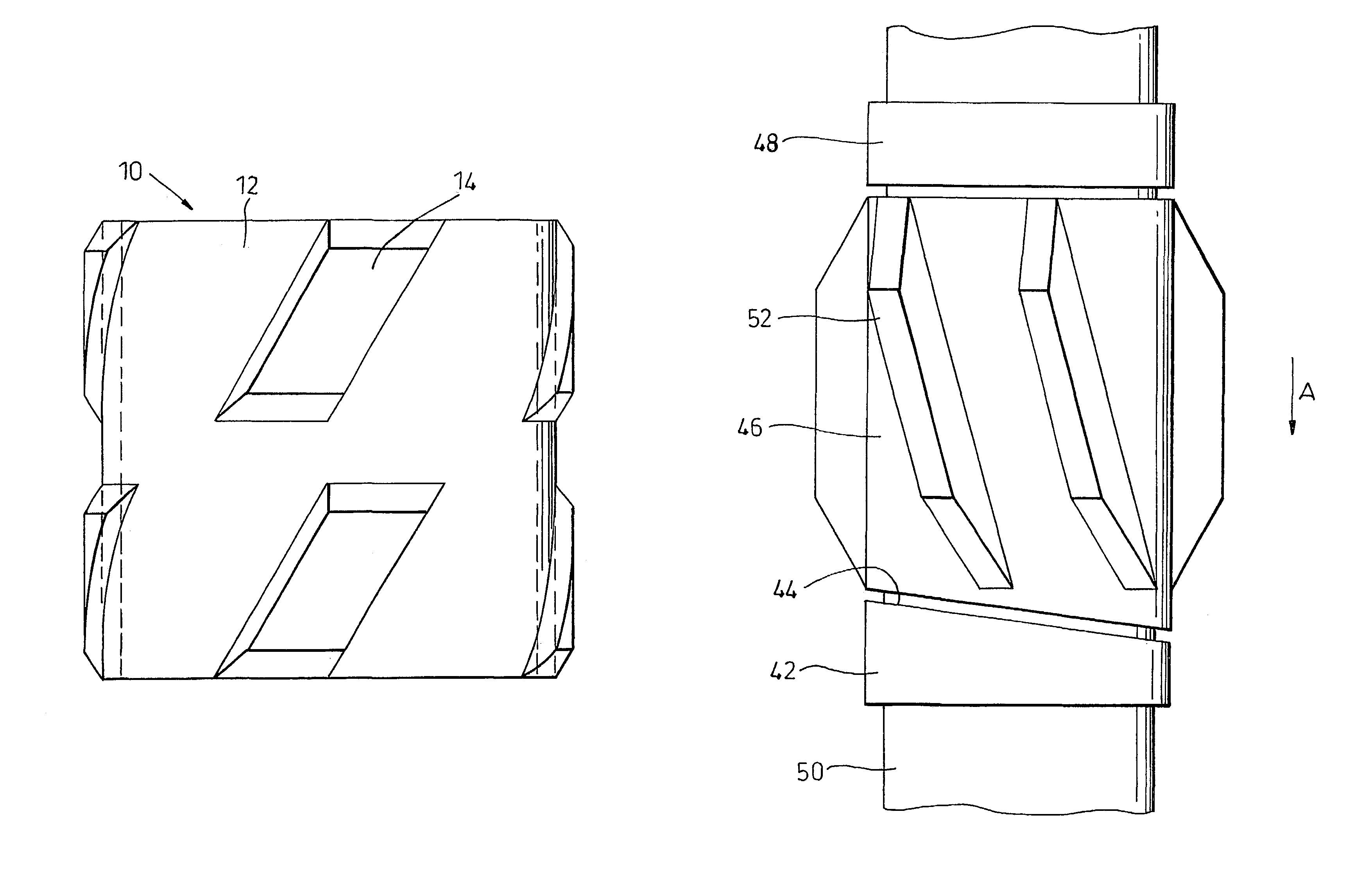
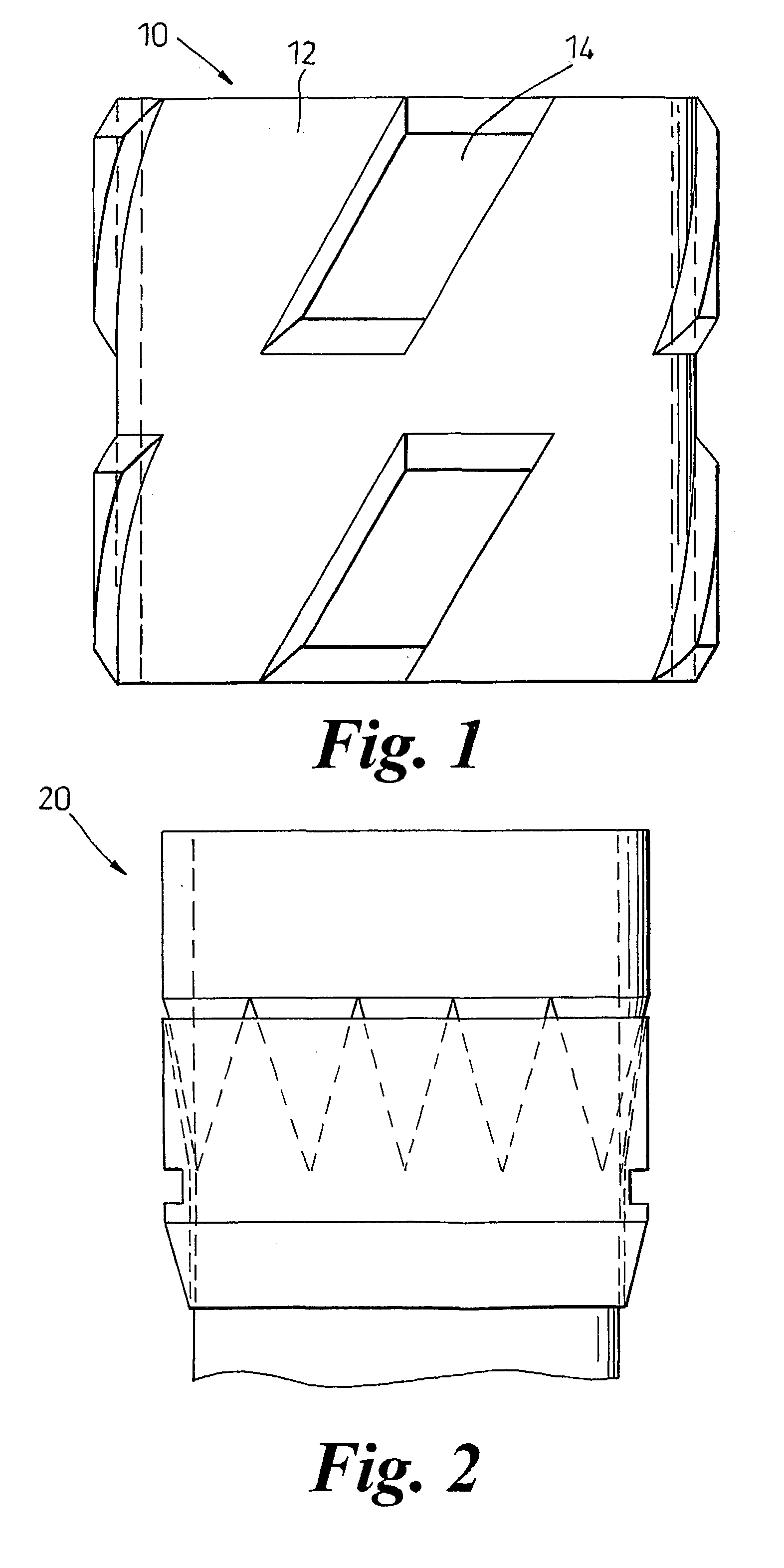
[0051]Referring first of all to FIG. 1, this shows a centraliser for mounting on a tubular, particularly casing, in accordance with an embodiment of the invention. The centraliser 10 comprises a cylindrical body 12, on which are mounted a plurality of blades 14. The body 12 in this example is made of steel, while the blades 14 are formed of a plastics material, such as Nylon 6.6. Alternatively, the blades may be formed homogeneously with the body, while the blades and / or the body may incorporate plastic or other low friction inserts or coating on or about the blades or body. Each blade is generally parallelogram-shaped, and stands proud of the surface of the body. The spaces between the blades 14 define an unbroken axial and circumferential flow path for flow of mud, cement, and other flowable preparations past the centraliser.

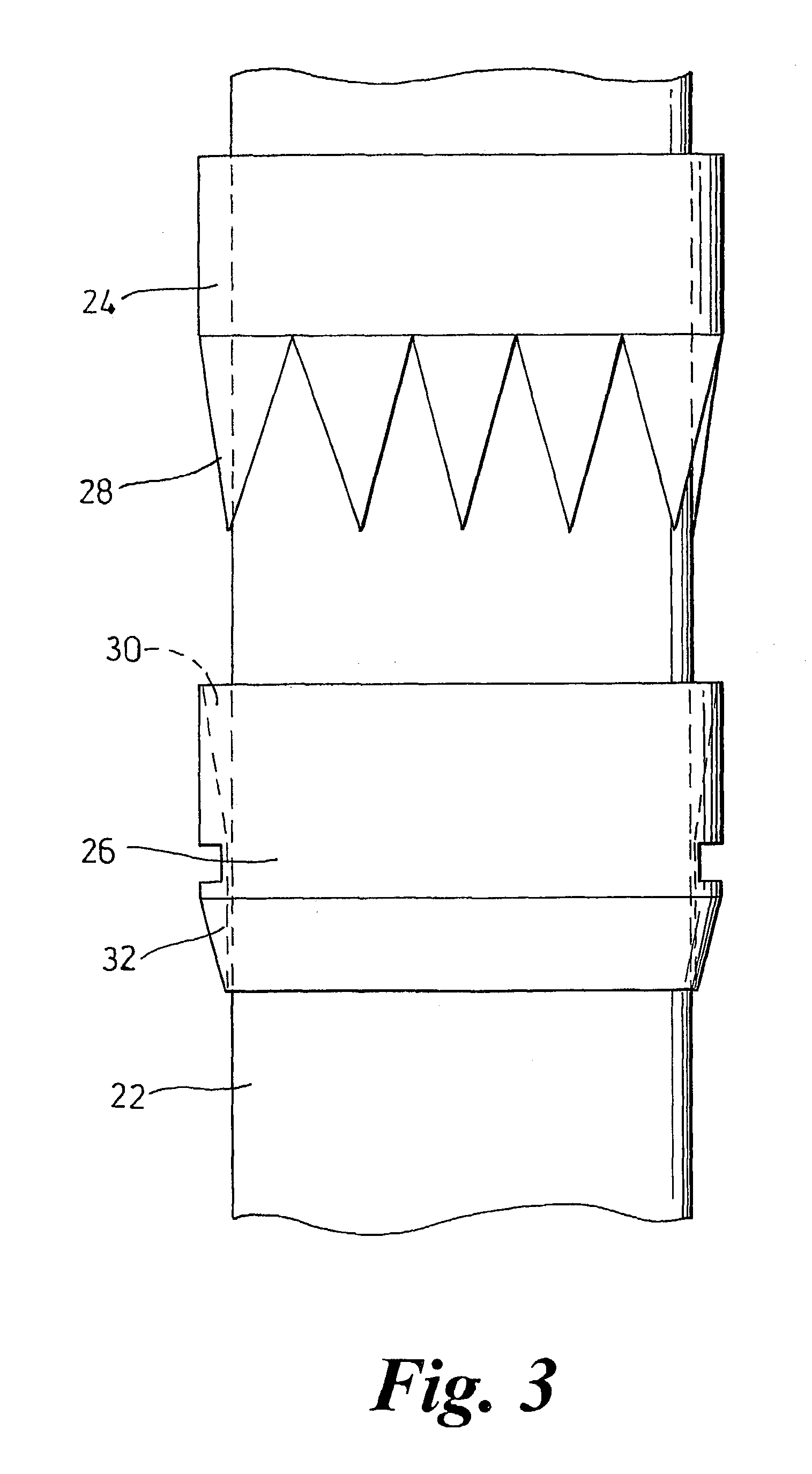
[0052]The centraliser 10 is provided in two sections which fit around a length of casing or drill pipe to enable the centraliser to be fitted and removed with...


PUM


Abstract

A centralizer 10 for mounting on a tubular member such as a section of casing, together with one or more stops 42, 48 for retaining the centralizer thereon. The stops 42, 48 are provided with profiles for engaging the centralizer to restrict rotation thereof. The centralizer 10 may be selectively permitted or restricted from rotation by selection of appropriate stops, and by relative movement of the stops and centralizer on the tubular. Certain embodiments of the centralizer 10 may also include blades 14 on the body thereof, the blades being formed such that the velocity and kinetic energy of fluid flow across the blades is altered, so reducing settling of drill cuttings within the bore and on the centralizer.

Description

FIELD OF THE INVENTION[0001]This invention relates to a centraliser for use when running tubulars into a drilled bore, and to other items that may be utilised in conjunction with centralisers.BACKGROUND OF THE INVENTION[0002]In the oil and gas exploration and production industry, subsurface hydrocarbon-bearing rock formations are accessed by bores drilled from surface. The drilled bores are lined with tubular members, conventionally metal tubing known as casing or liner; for brevity, reference will be made primarily herein to casing. The casing is typically cemented in the bore by passing a cement slurry up between the annulus between the casing and the bore wall.[0003]Any drilled bore will typically extend through a variety of formation types having different properties, for example formations which may swell after drilling to restrict the bore diameter, due to the chemical interaction with the drilling fluid. Also, when drilling between formations of different hardness, it is comm...

Claims


Application Information

Patent Timeline
IPC IPC(8): E21B17/10E21B10/46E21B17/14
CPCE21B17/1057
Inventor HERRERA, DEREK FREDERICK
Owner DEEP CASING TOOLS LTD
Why Eureka
Try Eureka