Reed valve for implantation into mammalian blood vessels and heart with optional temporary or permanent support

a technology of sigmoid valve and reed valve, which is applied in the field of one-way valves, can solve the problems of backflow, impaired function of sigmoid valve, and inability to fully support the heart, and achieve the effect of simplifying its implantation

Inactive Publication Date: 2007-01-09
THE INT HEART INST OF MONTANA FOUND
View PDF15 Cites 44 Cited by
  • Summary
  • Abstract
  • Description
  • Claims
  • Application Information

AI Technical Summary

Problems solved by technology

In disease, the function of the sigmoid valves is impaired either through narrowing of the valve (“stenosis”) or lack of complete closure, which results in backflow (“regurgitation”).
In both circumstances, the whole circulation of the blood and of the heart is altered giving rise to severe symptoms in the patient.
The technical difficulty of correctly implanting these stentless valves gave rise to the idea of mounting the porcine valves into a frame or stent made of metal or plastic covered with DACRON™ cloth.
The surgical techniques of implanting such stentless valves are far more demanding than when a standard stented valve is used.
The main technical difficulties are due to the floppiness of the valve, resulting in a defective implantation, and in the case of the aortic valve, interference with the coronary ostia.
These difficulties have significantly limited the use of stentless valves.
It soon became apparent that the main problem, different from the mitral valve, was the lack of sufficient valve tissue to achieve competence.

Method used


Image

  • Reed valve for implantation into mammalian blood vessels and heart with optional temporary or permanent support
  • Reed valve for implantation into mammalian blood vessels and heart with optional temporary or permanent support
  • Reed valve for implantation into mammalian blood vessels and heart with optional temporary or permanent support

Examples


second embodiment

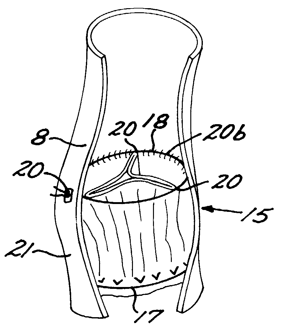
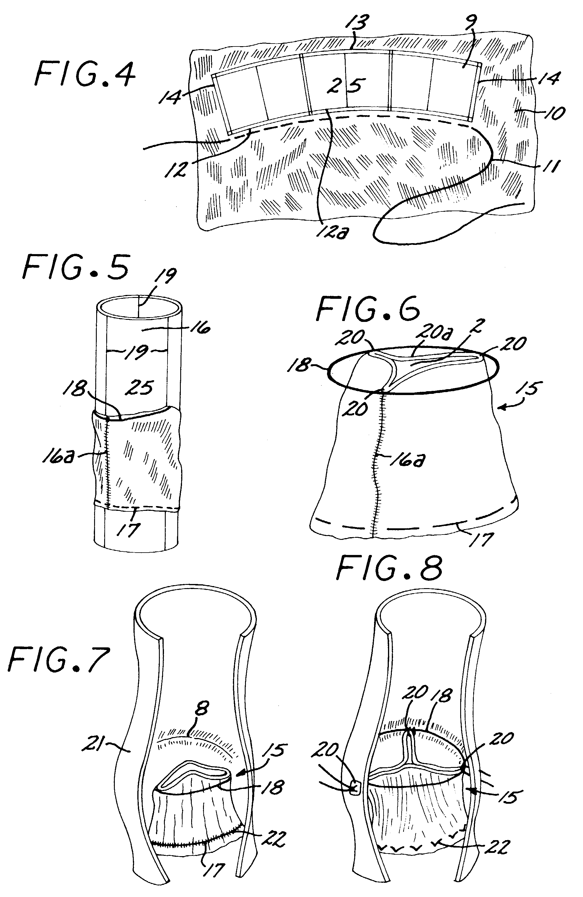
[0040]the holder of the present invention shown in FIGS. 10B and 10C) also includes three substantially equal chords that connect the inflow and outflow disks. These chords are located at the level of the commissures of the reed valve, and their length corresponds to the total height of the reed valve. The purpose of these two techniques (stopper or cords) for limiting the maximum distance between the disks (and therefore between the inflow and outflow orifices of the reed valve) is to achieve correct deployment of the reed valve without either folding it if the inflow and outflow orifices are too close or unduly stretching the tissue if the inflow and outflow orifices of the reed valve are too far apart.

first embodiment

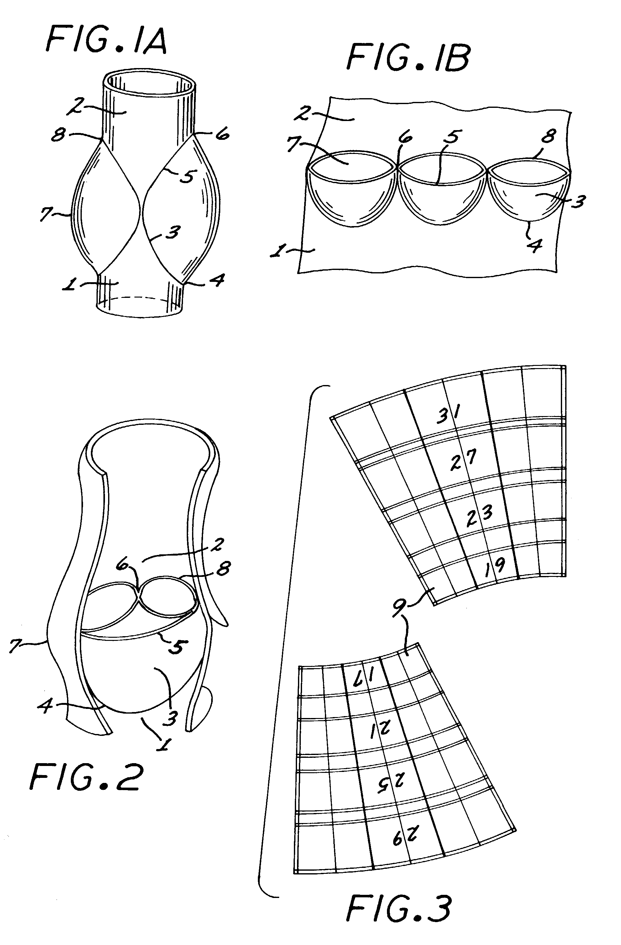
[0041]When the holder of the invention is used to support the valve by placing the holder inside the valve, then a mechanism or means need to be provided to temporarily reduce the effective diameter of the holder so that it can be inserted into the valve, and be removed from it to complete the surgical implantation process. The first embodiment shown in FIGS. 10A and 12A and 12C accomplishes this by virtue of the rings being contractible and expandable, as described in more detail below. In the second preferred embodiment shown in FIGS. 10B and 12B the disks are capable of changing their angle in relation to the rod (FIG. 12B). In one position the disks are at 45 degrees to the rod and in a second position the disks are perpendicular to the rod. The holder is introduced through the valve with the disks at 45 degrees and once in the correct location the disks are moved to the perpendicular (and wider) position.

[0042]The holder of the present invention can be disposable. Therefore, it...


PUM


Abstract

A multi-leaflet valve adapted to serve as a prosthesis for diseased native valve of a mammal is constructed of biologic membrane or of biocompatible synthetic membrane. The valve has the shape of a truncated cone that has an inflow and an outflow orifice with leaflets forming the outflow orifice and forming a plurality of commissures. A first flexible stent is removably affixed in a substantially circular fashion around the truncated cone in proximity of the inflow orifice, and a second flexible stent is removably affixed at the location of the commissures to form a circle around the truncated cone in proximity of the outflow orifice. The stents maintain the shape of the valve during the surgical implantation procedure. Each stent independently can be left in the valve or can be removed during the implantation procedure based upon the judgement of the cardiac surgeon performing the implantation procedure. A holder designed to maintain the geometry of the valve during implantation to a mammal is also disclosed.

Description

CROSS-REFERENCE TO PRIORITY APPLICATION[0001]The present application claims the priority of provisional application Ser. No. 60 / 373,171 filed on Apr. 16, 2002.BACKGROUND OF THE INVENTION[0002]1. Field of the Invention[0003]The present invention is in the field of one-way valves designed to replace diseased venous or arterial valves present in the circulatory system. More specifically, the present invention is directed to the replacement of the aortic, pulmonary, or peripheral vein valves. The present invention is also directed to a holder that maintains the valve's geometry during its surgical implantation and assists the surgeon to orient it correctly.[0004]2. Description of Background ArtThe Sigmoid Valves[0005]The mammalian circulation needs the presence of one-way valves to maintain forward blood flow. These valves are found in the outflow of the right and left ventricles (“pulmonary” and “aortic” valves, respectively) and in the large veins. Because of their similar anatomic st...

Claims


Application Information

Patent Timeline
Patent Type & Authority Patents(United States)
IPC IPC(8): A61F2/06A61B19/00A61F2/24
CPCA61F2/2412A61F2/2415A61F2/243A61F2/2475A61F2/2427A61F2/2418A61F2220/0075
Inventor DURAN, CARLOS
Owner THE INT HEART INST OF MONTANA FOUND
Why Eureka
Try Eureka