Implantable medical balloon and valve

a technology of balloons and valves, applied in the field of implantable micro-balloons, can solve the problems of fatigue, laborious and expensive manufacturing methods, and separation of adhesives, and achieve the effects of increasing reliability and cost efficiency, and simple construction and manufacturing

Active Publication Date: 2007-01-09
BOSTON SCI SCIMED INC
View PDF72 Cites 13 Cited by
  • Summary
  • Abstract
  • Description
  • Claims
  • Application Information

AI Technical Summary

Benefits of technology

[0009]Provided is a microballoon which is relatively simple in construction and manufacture and provides an increased level of reliability and cost efficiency. The microballoon generally comprises a valve portion of unitary construction, which is a molded valve body made of a material, such as silicone, capable of being punctured and resealed. The valve portion includes a cylindrical wall extending therefrom having an open end which is constructed and arranged such that when the open end is dipped into a solution of material, such as silicone, a meniscus forms over the end.

Problems solved by technology

Until now, the small size and numerous intricacies of microballoons have presented problems pertaining to performance and manufacture.
Such a manufacturing method is laborious and expensive.
Moreover, when the balloons are inflated, there is a tendency for the adhesive to fatigue, separate and allow the fluid contained within the balloon chamber to leak.
Even when the adhesive holds, however, the valve can leak due to manufacturing defects that can result from the complexity and size of the valve.

Method used


Image

  • Implantable medical balloon and valve
  • Implantable medical balloon and valve
  • Implantable medical balloon and valve

Examples


Embodiment Construction

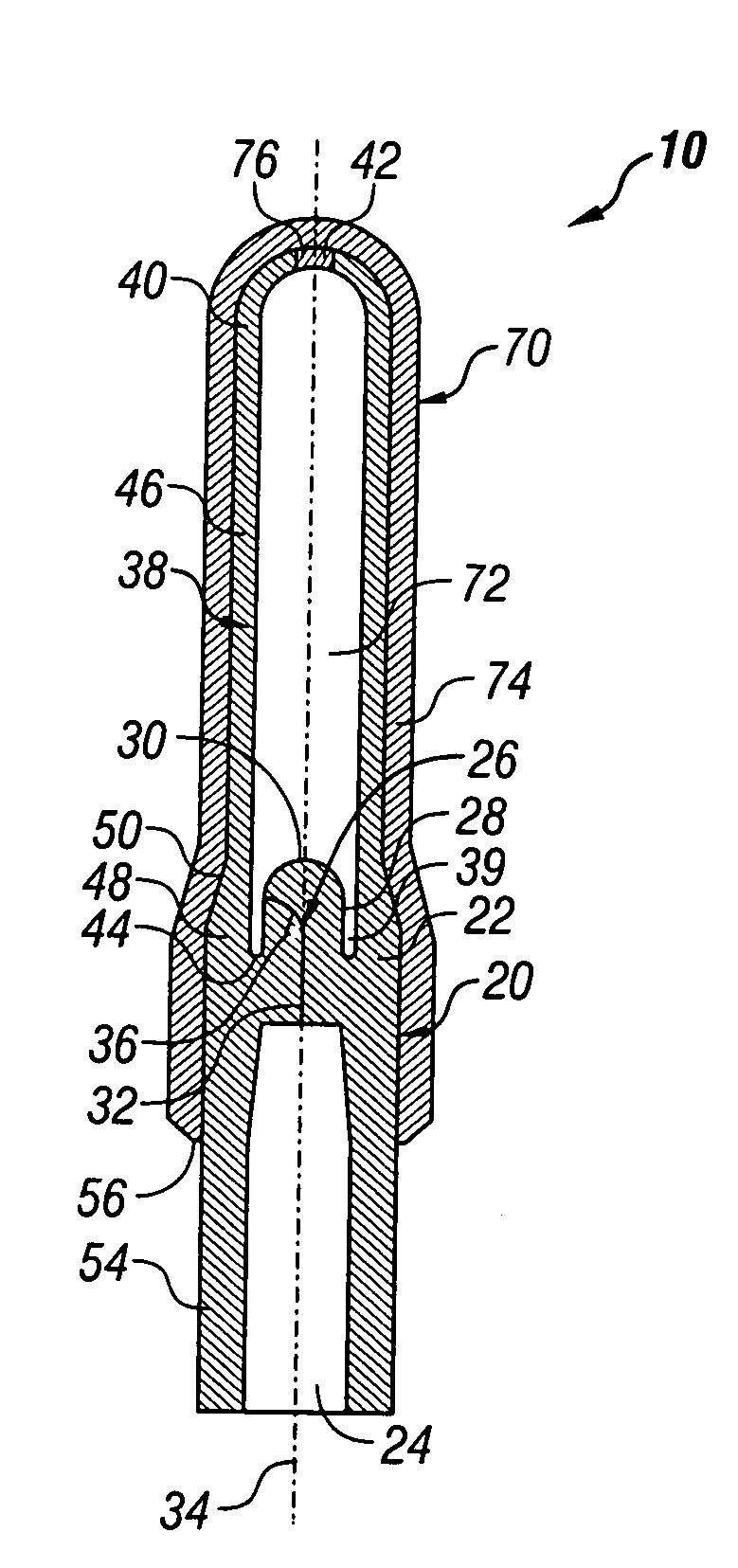
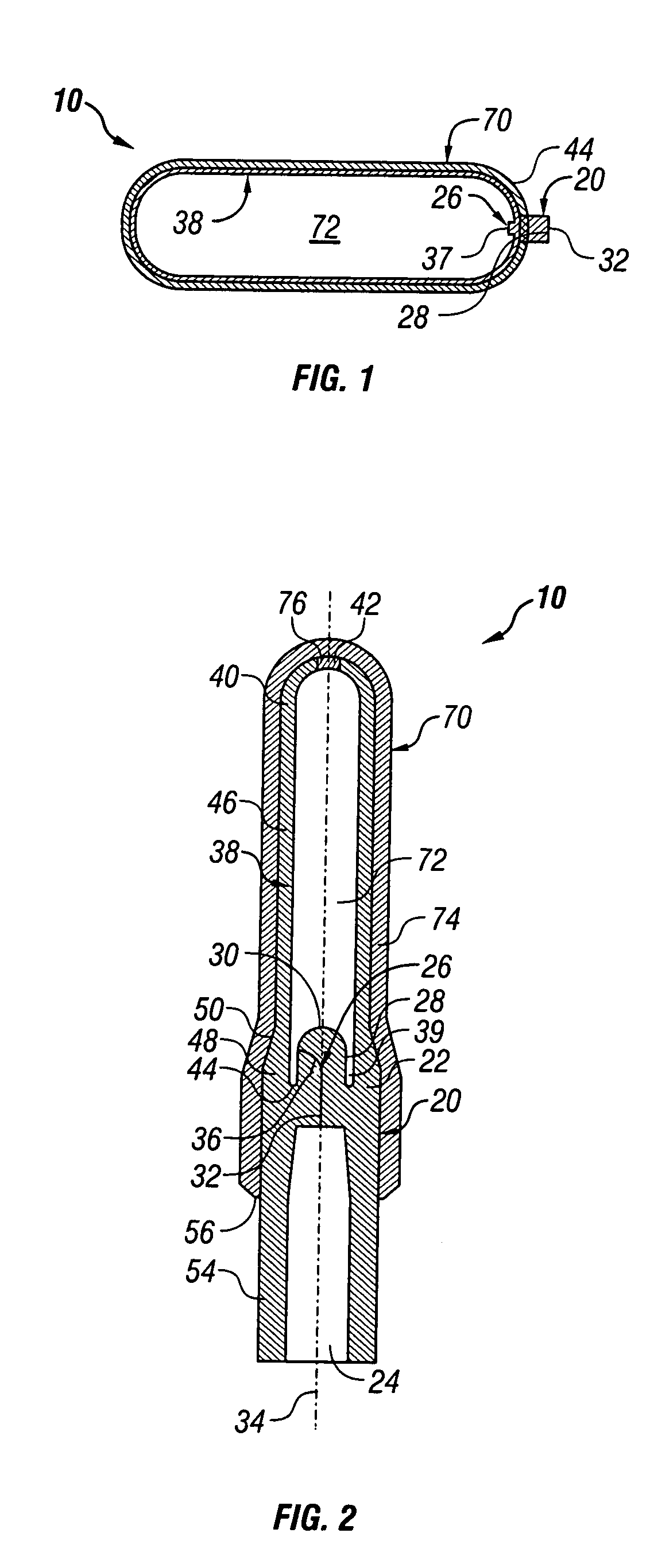
[0020]Referring now to the Figures, and first to FIG. 1, there is shown a completed device 10 of the present invention in an inflated state. Device 10 generally comprises a valve portion 20 and a balloon portion 70.

[0021]FIG. 2 provides a detailed depiction of the device 10 in a deflated state and prior to its first inflation. The valve portion 20 is of unitary construction and includes a valve body 22 and a valve stem 26. The valve body 22 is preferably cylindrical and defines an inlet 24 in its lower side. The inlet 24 is cylindrical, frustoconical, conical, semispherical, or a similar suitable shape, and substantially concentric with the valve body 22.

[0022]The valve stem 26 is integral with the valve body 22 and extends upwardly therefrom, opposite the inlet 24. The valve stem 26 has at least one side 28 and a tip 30. Preferably, the valve stem 26 is cylindrical and the tip 30 is rounded, thereby forming somewhat of a silo shape. The valve stem 26 is substantially concentric wit...


PUM

PropertyMeasurementUnit
elastomericaaaaaaaaaa
diameteraaaaaaaaaa
inner diameteraaaaaaaaaa

Abstract

A medical balloon, implantable in human tissue, of unitary silicone construction. The balloon is self-sealing upon removal of an inflation implement. The balloon device comprises a molded valve portion which is dip-coated in a silicone dispersion to create a balloon wall around and integral with the valve portion. Preferably, both the valve portion and the balloon wall are comprised of the same silicone material. The dipping process, combined with a vulcanizing process, creates a laminar wall which is strong and resistant to separation during inflation. The balloons may be used in for the treatement of urinary incontinence or vesicoureteral reflux, alternative procedures such as emboliztion or blocking of veins or arteries to accomplish the treatement of enlarged blood vessels in the brain or for treating severe uterine bleeding.

Description

CROSS REFERENCE TO RELATED APPLICATIONS[0001]This application claims priority to U.S. provisional patent application No. 60 / 291,493, filed May 15, 2001 which is incorporated by reference herein.BACKGROUND OF THE INVENTION[0002]The present invention pertains generally to an implantable microballoon and a method of making such a microballoon.[0003]Implantable microballoons provide a minimally invasive treatment for the urological condition of stress urinary incontinence resulting from Intrinsic Sphincter Deficiency (ISD). Treatment of the condition is completed through placement of one or more implantable balloons into the periurethral tissue of the bladder neck. Implantation of the balloons results in the coaptation of the urethra which improves or resolves the incontinence condition.[0004]Delivery is completed by insertion of the microballoon into the tissue parallel to the urethra. The microballoon is then inflated and left in the bladder neck.[0005]Microballoons can be similarly u...

Claims


Application Information

Patent Timeline
Patent Type & Authority Patents(United States)
IPC IPC(8): A61F2/02A61F2/04A61F2/00
CPCA61F2/0027Y10T29/49405
Inventor MORNINGSTAR, RANDY L.
Owner BOSTON SCI SCIMED INC
Why Eureka
Try Eureka