Johnson reversible engine

a reversible engine and engine technology, applied in the field of reversible engines, can solve the problems of inability to use cells, fuel cell types suffer, and the electrochemical cells have had a problem of exhausting reactants, etc., and achieve the effect of increasing pressur

Inactive Publication Date: 2007-01-09
JTEC ENERGY INC
View PDF14 Cites 56 Cited by
  • Summary
  • Abstract
  • Description
  • Claims
  • Application Information

AI Technical Summary

Benefits of technology

[0009]In a preferred form of the invention a reversible engine comprises a first electrochemical cell, a second electrochemical cell and a conduit system. The first electrochemical cell has a first ion conductive material, a first electrode mounted upon one side of the first ion conductive material, a second electrode mounted upon one side of the first ion conductive material opposite the first electrode. The second electrochemical cell has a second ion conductive material, a third electrode mounted upon one side of the second ion conductive material, and a fourth electrode mounted upon one side of the second ion conductive material opposite the third electrode. The conduit system has a first conduit and a second conduit. The first conduit has one end in fluid communication with the first electrochemical cell second electrode and a second end in fluid communication with the second electrochemical cell third electrode. The second conduit has one end in fluid communication

Problems solved by technology

Electrochemical cells however have had a problem of exhausting the reactants.
During the recharging of the cell the cell typically is not usable.
These types of fuel cells however suffer from a number of disadvantages.
Additionally, these cells produce a continuous product stream which must be removed, the removal of which may pose a problem.
However, over time these porous electrodes can become fouled or plugged so as to slow or even prevent the passage of the reactant.
Such slowing of the reactant flow reduces the production of electricity.
Lastly, the selection of an appropriate electrolyte is not always easy.
Frequently, the limited migration of the ionized

Method used


Image

  • Johnson reversible engine
  • Johnson reversible engine
  • Johnson reversible engine

Examples


Embodiment Construction

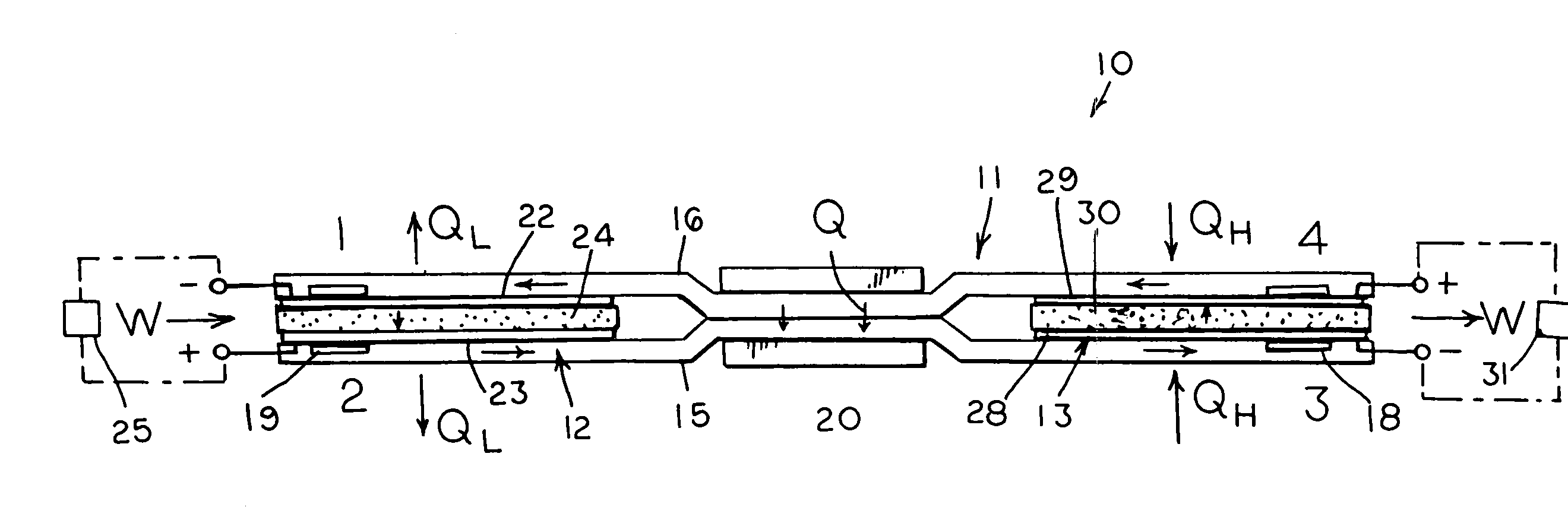
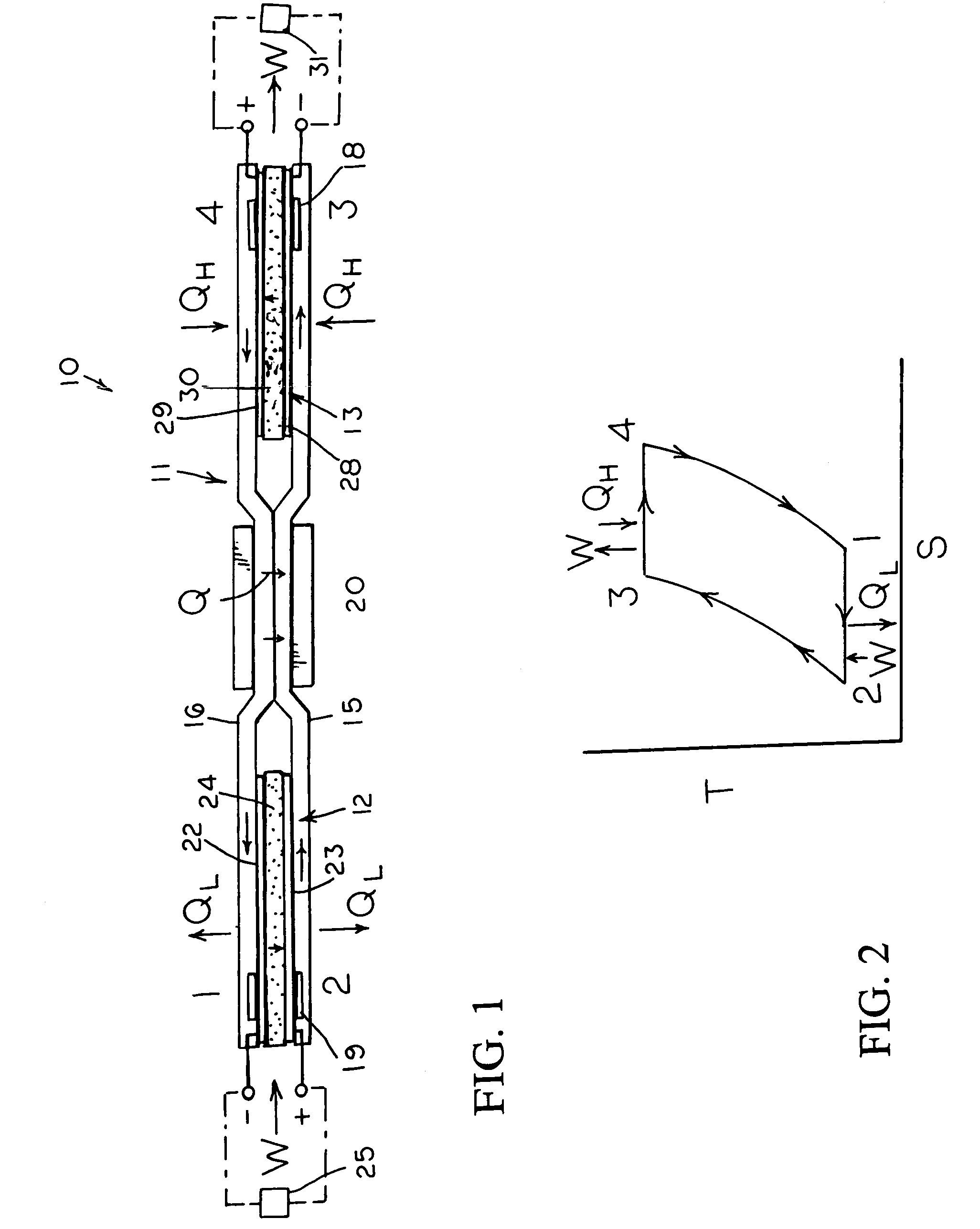
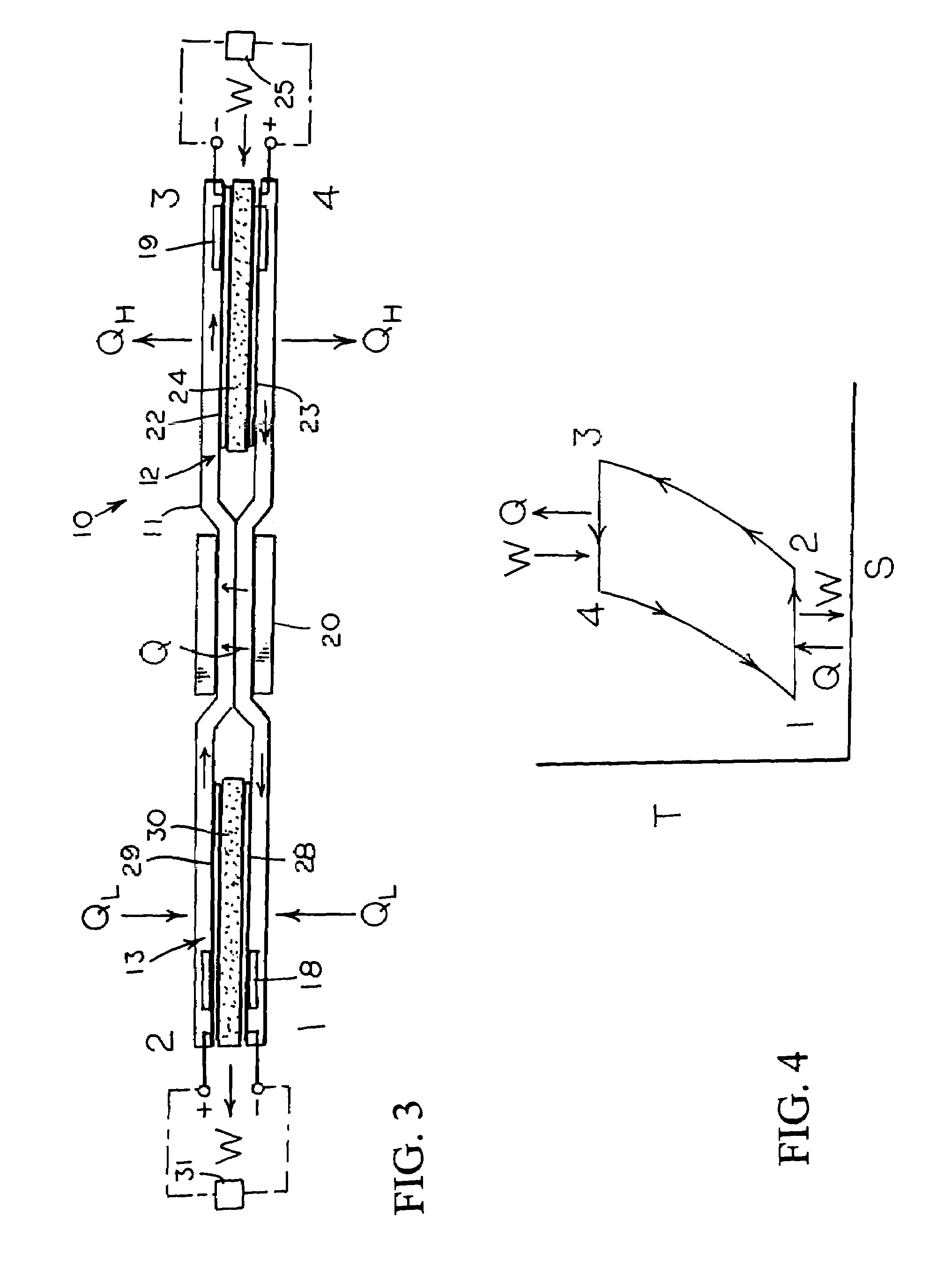
[0014]With reference next to the drawings, there is shown in FIG. 1 a reversible engine 10 in a preferred form of the invention of a heat engine. The engine 10 has a conduit system 11, a first electrochemical cells 12, and a second electrochemical cell 13. The conduit system 11 is made of a non-reactive material such as stainless steel. The conduit system 11 includes a first conduit 15 extending from the first electrochemical cell 12 to the second electrochemical cell 13, and a second conduit 16 extending from the second electrochemical cell 13 to the first electrochemical cell 12.

[0015]The heat engine 10 also includes a heater 18 mounted in thermal communication with the conduit system 11 adjacent the second electrochemical cell 13, a cooler 19 mounted in thermal communication with the conduit system 11 adjacent the first electrochemical cell 12, and a heat regenerator or exchanger 20 thermally coupled to the first and second conduits 15 and 16 for the transfer of heat therebetween...


PUM


Abstract

An reversible engine (10) is disclosed having a conduit system (11), a first electrochemical cells (12), and a second electrochemical cell (13). The conduit system (11) includes a first conduit (15) extending from the first electrochemical cell (12) to the second electrochemical cell (13), and a second conduit (16) extending from the second electrochemical cell (13) to the first electrochemical cell (12). The heat engine (10) also includes a heater (18) mounted in thermal communication with the conduit system (11) adjacent the second electrochemical cell (13), a cooler (19) mounted in thermal communication with the conduit system (11) adjacent the first electrochemical cell (12), and a regenerative heat exchanger (20) thermally coupled to the first and second conduits (15) and (16) for the transfer of heat therebetween.

Description

REFERENCE TO RELATED APPLICATION[0001]This is a continuation-in-part of U.S. patent application Ser. No. 09 / 627,721, filed Jul. 28, 2000 now abandoned.TECHNICAL FIELD[0002]This invention relates to the conversion of heat energy to electrical energy or electrical energy to heat energy utilizing a reversible engine having a pair of electrochemical cells.BACKGROUND OF THE INVENTION[0003]The conversion of heat energy or chemical energy to electrical energy, or visa-versa, may be accomplished in a variety of ways. It is known that electrochemical cells or batteries rely on redox reactions wherein electrons from a reactant being oxidized are transferred to a reactant being reduced. With the separation of the reactants from each other, it is possible to cause the electrons to flow through an external circuit where they can be used to perform work.[0004]Electrochemical cells however have had a problem of exhausting the reactants. Although cells can be designed to be recharged by applying a ...

Claims


Application Information

Patent Timeline
IPC IPC(8): H01M8/04H01M6/36F25B23/00F25B30/00H01M8/02H01M8/10H01M14/00
CPCF25B23/00H01M8/04074H01M8/04014F25B30/00Y02E60/50H01M8/04089H01M14/00H01M6/36
Inventor JOHNSON, LONNIE G.MULLER, JAMES R.
Owner JTEC ENERGY INC
Why Eureka
Try Eureka