Battery pack

Inactive Publication Date: 2007-01-09
SANYO ELECTRIC CO LTD
View PDF24 Cites 24 Cited by
  • Summary
  • Abstract
  • Description
  • Claims
  • Application Information

AI Technical Summary

Benefits of technology

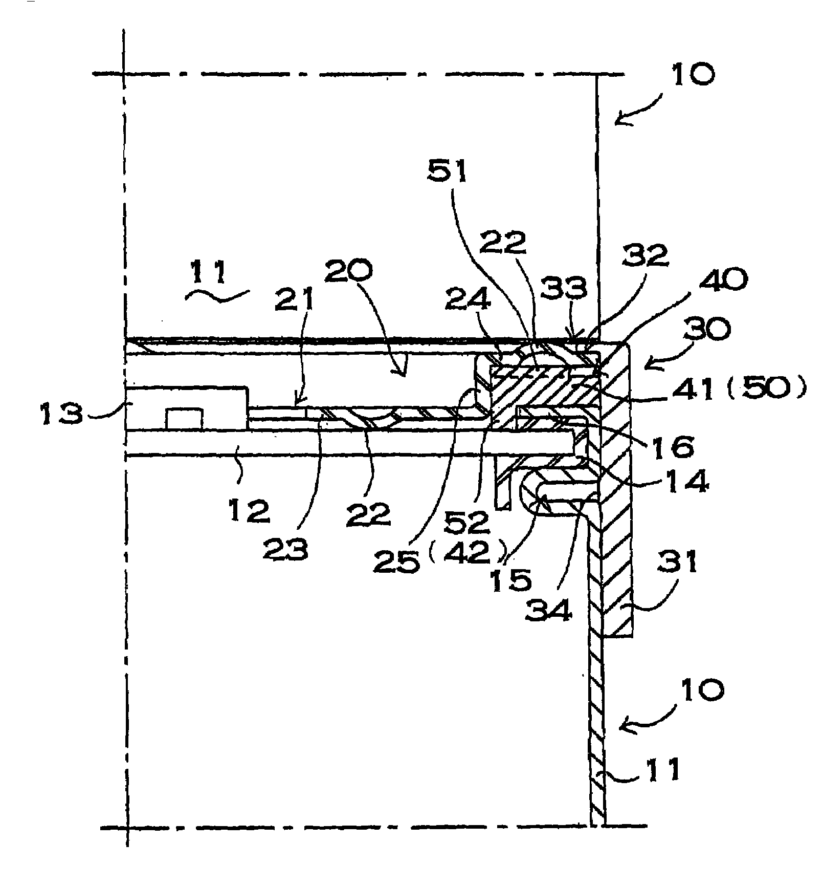
[0008]The connector may be provided with welding convex portions to be welded to the batteries on the inner peripheral portion and on the outer peripheral portion in such a manner that the welding convex portion on the inner peripheral portion and the welding convex portion on the outer peripheral portion are located in close proximity to each other. Further, the connector may be provided with a plurality of welding convex portions on one of the inner peripheral portion and the outer peripheral portion, so that notch portions are made between the adjacent welding convex portions. Furthermore, the battery pack may be provided with an insulator disposed between the outer peripheral portion of the connector and the caulking convex strip. This battery pack makes it possible to forestall shorting in a reliable manner by preventing the connector from coming in contact with the caulking convex strip.
[0009]Moreover, the battery pack may be provided with a connector and a holder cap for an insulator both disposed between the batteries to be interlocked linearly. This battery pack permits the batteries to be interlocked efficiently while the connector and the insulator are held by the holder cap.
[0010]The battery pack of the above-described structures has the advantage that the batteries can be interlocked securely in a reliable manner through welding in a simple and easy way while being electrically connected in a low resistance state. This is because the battery pack is arranged in such a manner that the

Problems solved by technology

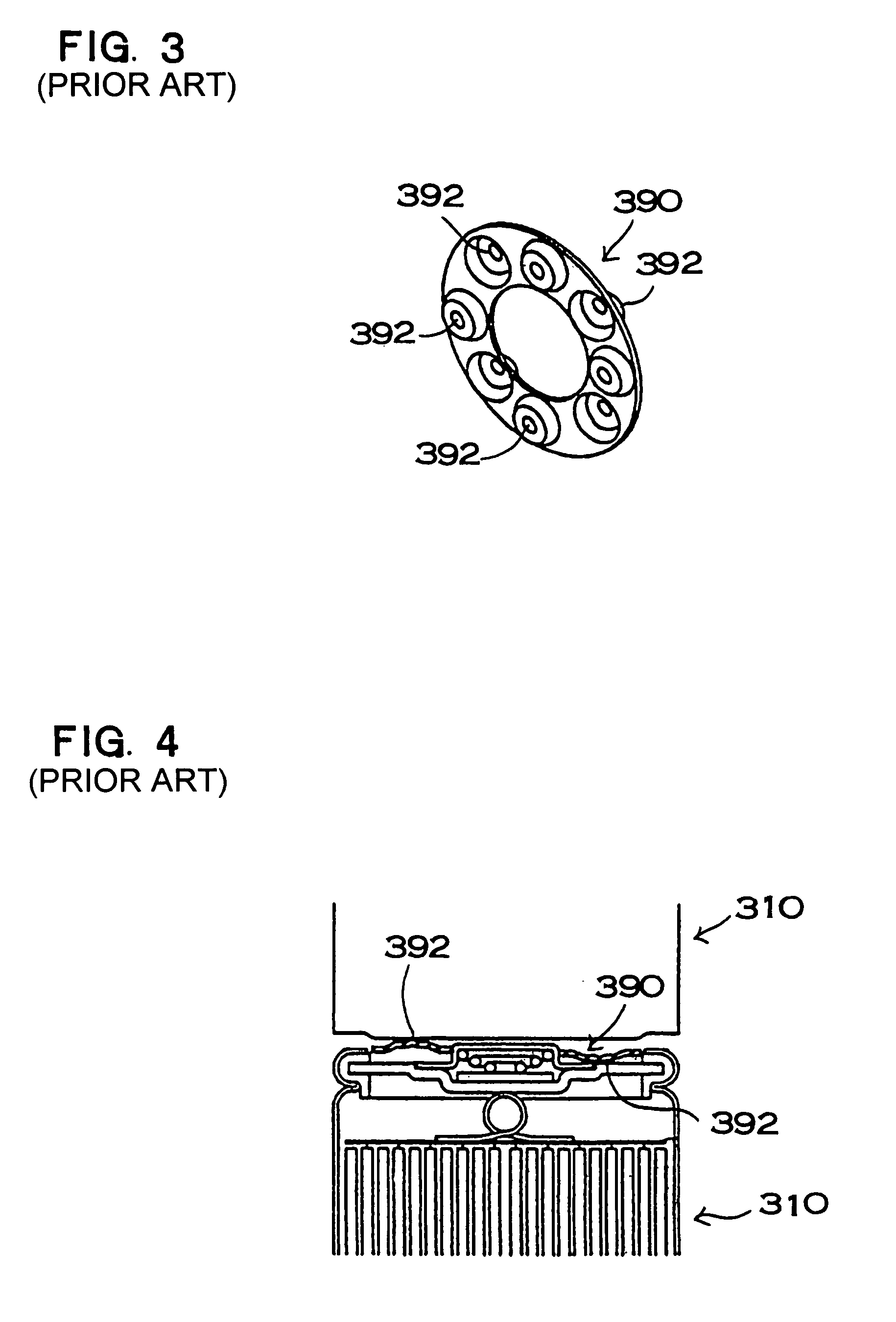
Large connection resistance not only reduces an output from the battery pack, but also gives rise to heat generation through Joule heating; moreover, losses due to resistance make the power utilization less efficient.
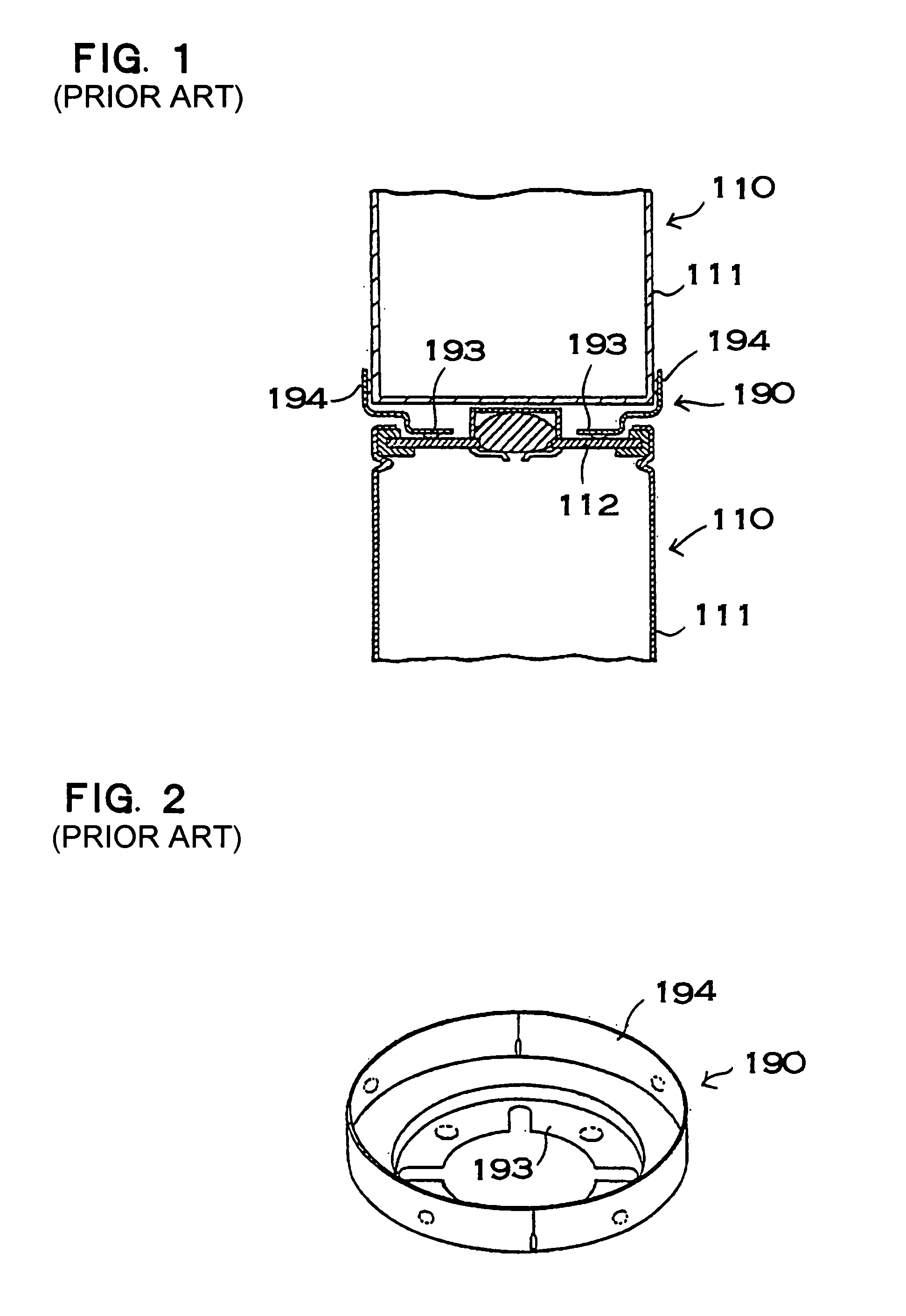
For this reason, this battery pack has a drawback in that the connecting process of the metal cap cannot be any simpler.
Further, this battery pack has another drawback in that the metal cap of this structure has a distance from the spot welding positions on the flat portion 193 to t

Method used


Image

  • Battery pack
  • Battery pack
  • Battery pack

Examples


Example

[0027]A battery pack shown in FIG. 5 is composed of a plurality of series-connected and linearly interlocked secondary batteries 10. More than one battery pack of this structure is connected in series and chiefly used in a motor vehicle, such as a hybrid car. It should be appreciated, however, that the battery pack of the invention can be used in an application in which a large output is needed other than a motor vehicle. The battery pack shown in FIG. 5 is composed of series-connected and linearly interlocked secondary batteries of cylindrical batteries. It should be appreciated, however, that the battery pack may be composed of series-connected and linearly interlocked secondary batteries of prismatic batteries.

[0028]As shown in FIG. 6, the battery packs are aligned in parallel on the same flat plane and accommodated in a casing 70. The battery packs aligned crosswise are connected with one another in series and thereby raise an output voltage. Each battery pack is fixed to the ca...


PUM


Abstract

A battery pack includes a plurality of batteries interlocked linearly through a connector. The connector includes an inner peripheral portion to be welded to one battery, and an outer peripheral portion, provided outside the inner peripheral portion, to be welded to the other battery. The inner peripheral portion and the outer peripheral portion have a step in between, and the step places the inner peripheral portion in a concave portion of the connector. The inner peripheral portion of the connector is located interiorly of a caulking convex strip provided at an end face of one battery, and an inner peripheral portion is connected to the battery end face through welding without coming in contact with the caulking convex strip. The outer peripheral portion is connected to an outer peripheral portion of a battery end face of the other battery through welding.

Description

[0001]This application is based on applications No. 17899 filed on Jan. 28, 2002, No. 20604 filed on Jan. 29, 2002, No. 22508 filed on Jan. 30, 2002, No. 23227 filed on Jan. 31, 2002 and No. 23228 filed on Jan. 31, 2002 in Japan, the content of which incorporated hereinto by reference.BACKGROUND OF THE INVENTION[0002]The present invention relates to a battery pack composed of a plurality of linearly interlocked batteries.[0003]A battery pack composed of linearly interlocked secondary batteries is chiefly used in a motor vehicle, such as a hybrid car. For the battery pack of this structure, it is important to interlock the secondary batteries securely in a low resistance state. Large connection resistance not only reduces an output from the battery pack, but also gives rise to heat generation through Joule heating; moreover, losses due to resistance make the power utilization less efficient. JP-A-10-106533 discloses a structure using a connector for a battery pack composed of linearl...

Claims


Application Information

Patent Timeline
IPC IPC(8): H01M2/10H01M6/42H01M6/02H01M10/052H01M10/30H01M10/34H01M50/503H01M50/516H01M50/522H01M50/526H01M50/528H01M50/529H01R3/00H01R31/08
CPCH01M2/206H01M2/105H01M6/42Y02T10/7011H01M10/30H01M10/345H01R31/085H01M10/052Y02E60/10H01M50/213H01M50/522H01M50/526H01M50/516H01M50/503H01M50/50
Inventor KUNIMOTO, KIYOSHITOYA, SHOICHIKOUNO, SABUROUEKI, YUTAKA
Owner SANYO ELECTRIC CO LTD
Why Eureka
Try Eureka