
Systems and methods for determining the existence of a visible plume from the chimney of a facility burning carbon-based fuels

a technology of carbon-based fuels and detection methods, which is applied in the direction of mechanical power/torque control, ratio control, temperatue control, etc., can solve the problem that optical based opacity monitors may not detect plumes caused by excess oxygen, and achieve the effect of increasing the accuracy of plume detection

Active Publication Date: 2007-01-09
FLORIDA POWER & LIGHT
View PDF22 Cites 14 Cited by
  • Summary
  • Abstract
  • Description
  • Claims
  • Application Information

AI Technical Summary

Benefits of technology

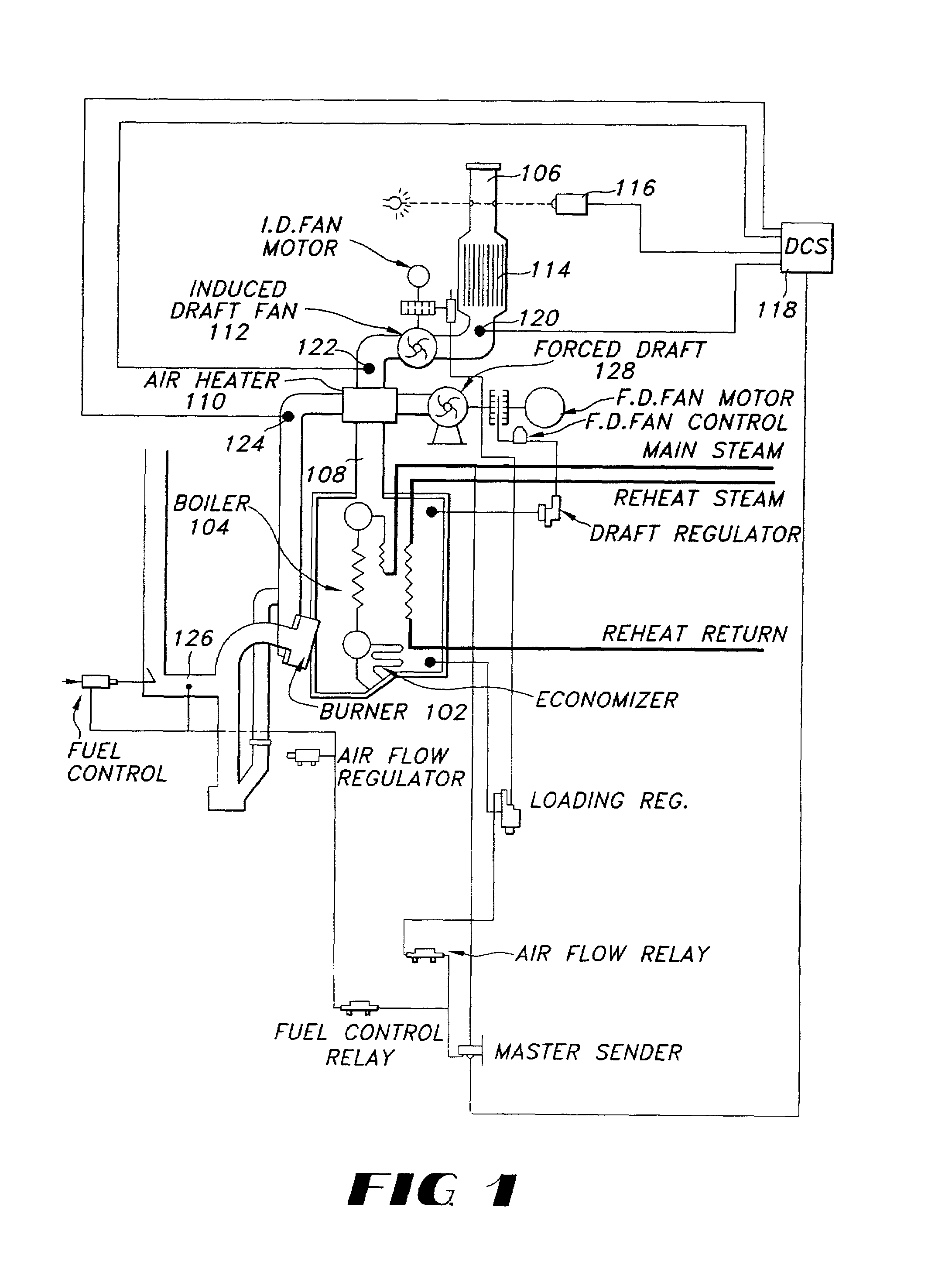
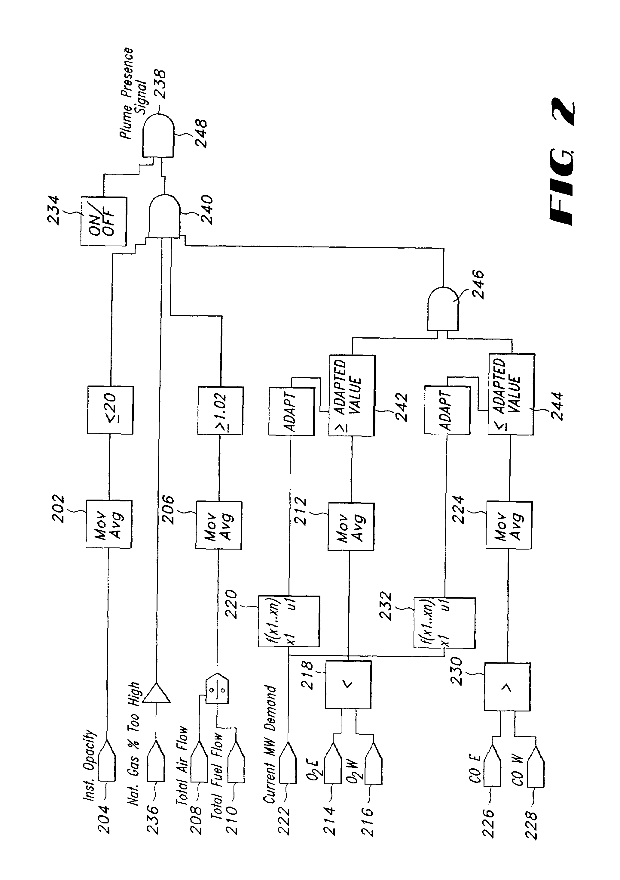
[0008]One aspect of the present invention relates to a system that receives inputs from the combustion process and makes a determination based upon these inputs whether a visible plume of exhaust gasses exist at the facility's stack. In one embodiment, the system receives at least total air and total fuel flow into the combustion chamber of the facility as inputs. The system calculates a ratio of total air flow to total fuel flow and compares this ratio to a predetermined value to determine the presence of a visible plume. Other aspects of the system may incorporate additional inputs such as one or more of opacity from an opacity monitor, oxygen content and carbon monoxide content in the exhaust stream to increase the accuracy of the detection of the plume. These systems may be incorporated into the facility's control system or they may stand alone.
[0009]Another aspect of the invention relates to methods for detecting and signaling the presence of a visible plume at the stack of a facility burning carbon-based fuels. These methods rely upon combustion control parameters that may be pre-existing in many power generation facilities. In one embodiment, a method is disclosed to determine the presence of a visible plume from a ratio of the total air and total fuel flow into the combustion chamber of the facility. Other methods may incorporate with the total air flow to total fuel flow ratio additional combustion control parameters such as one or more of opacity from an opacity monitor, oxygen content and carbon monoxide content in the exhaust stream to increase the accuracy of the detection of the plume.

Problems solved by technology

Traditional, optical based opacity monitors may not detect plumes caused by excess oxygen in the combustion process.

Method used


Image

  • Systems and methods for determining the existence of a visible plume from the chimney of a facility burning carbon-based fuels
  • Systems and methods for determining the existence of a visible plume from the chimney of a facility burning carbon-based fuels
  • Systems and methods for determining the existence of a visible plume from the chimney of a facility burning carbon-based fuels

Examples


Embodiment Construction

[0019]The present invention now will be described more fully hereinafter with reference to the accompanying drawings, in which preferred embodiments of the invention are shown. This invention may, however, be embodied in many different forms and should not be construed as limited to the embodiments set forth herein; rather, these embodiments are provided so that this disclosure will be thorough and complete, and will fully convey the scope of the invention to those skilled in the art. Like numbers refer to like elements throughout.

[0020]The present invention relates to systems and methods to detect a visible plume of exhaust gasses at the stack of a facility burning carbon-based fuels. Unlike previous systems and methods, the present invention does not attempt to directly detect the plume through only optical means but utilizes combustion control parameters that are generally pre-existing in power generation facilities. Furthermore, the system may readily be incorporated into a faci...


PUM


Abstract

Excess oxygen in the combustion process of a facility that bums carbon-based fuels may cause a visible plume in the atmosphere at the stack of the facility. Traditional optical based opacity monitors may be unable to detect this plume or the plume may form at a location downstream from the opacity monitor toward the stack. The present invention discloses methods to utilize common combustion control variables to detect and signal the presence of a visible plume of exhaust gasses. Also disclosed are systems that detect the visible plume and provide a signal so that the combustion process may be manually or automatically adjusted to reduce or eliminate the visible plume.

Description

FIELD OF THE INVENTION[0001]This invention generally relates to the detection of a visible plume emitted from smokestacks or chimneys of power generating facilities.BACKGROUND OF THE INVENTION[0002]Opacity monitors are used in facilities wherein exhaust gasses from the combustion of carbon-based fuels can release pollutants into the atmosphere through the facility's chimney. Generally, such opacity monitors utilize an optical detection system that measures opaqueness in the stream of exhaust gasses across the chimney or across an exhaust duct leading to the chimney. The opacity monitor creates an electronic signal that is proportionate, either directly or inversely, to the opaqueness detected in the exhaust stream. This electronic signal is used for automatic or manual control of the facility and the combustion process and for other facility operations or reporting purposes.[0003]Opacity monitors do not have the ability to measure or indicate the appearance of the emission of exhaus...

Claims


Application Information

Patent Timeline
IPC IPC(8): G01N21/00F01N3/00F23C3/00F23K3/02F23N1/00F23N1/02F23N1/08F23N5/00G01N15/06G01N21/49G01N21/85G05D11/00G05D17/00G05D21/00G05D23/00G05D3/12G05D5/00G05D9/00F23N5/18G01N21/59
CPCF23N1/022G01N21/59F23N5/003F23N2005/181
Inventor SCHULTZ, PAUL CLARENCE
Owner FLORIDA POWER & LIGHT
Learn More