Constituent parts assembling method for an actuating apparatus

a technology of assembling method and actuating apparatus, which is applied in the direction of nuclear energy welding apparatus, machines/engines, process and machine control, etc., can solve the problems of insufficient achievement of the required exhaust gas purification function, inability to sufficiently correct the difference in injection amount, and limited items that can be corrected by the electronic control unit, so as to achieve a wide operating range of the engine and reduce individual differences among the manufactured injectors.

Inactive Publication Date: 2007-01-09
DENSO CORP
View PDF14 Cites 11 Cited by
  • Summary
  • Abstract
  • Description
  • Claims
  • Application Information

AI Technical Summary

Benefits of technology

[0016]By adopting the above-described constituent parts assembling method for an actuating apparatus, it becomes possible to attain desired output characteristics through assembling processes of a plurality of constituent parts.
[0017]Namely, the present invention makes it possible to assure desired output characteristics for an actuating apparatus even when this apparatus includes numerous mechanical constituent parts and accordingly output characteristics are not easily adjustable through electric adjustment only.
[0022]Accordingly, it is unnecessary to execute the conventional correction performed by the electronic control unit which includes the step of picking up some correction points on the three-dimensional map defined by fuel pressure, injection pulse, and injection amount. Thus, a desired injection amount is obtained in a wide operating range of an engine. Furthermore, it enables to set the injection rate of each injector to desired output characteristics and accordingly the individual differences among the manufactured injectors can be reduced greatly. It enables to obtain a desired injection amount, desired injection start timing, and desired injection stop timing in a wide operating range of an engine. It becomes possible to attain the required exhaust gas purification function.

Problems solved by technology

When the correction point excurses or deviates out of the map, it is difficult to sufficiently correct the injection amount differences caused due to individual differences of respective injectors.
Furthermore, the items that can be corrected by the electronic control unit are limited to the injection amount and the injection timing in response to the injection command.
Accordingly, the required exhaust gas purification function cannot be attained satisfactorily.

Method used


Image

  • Constituent parts assembling method for an actuating apparatus
  • Constituent parts assembling method for an actuating apparatus
  • Constituent parts assembling method for an actuating apparatus

Examples


first embodiment

[0060]A preferred embodiment and a modified embodiment of the present invention will be explained based on an injector of an accumulator fuel injection system.

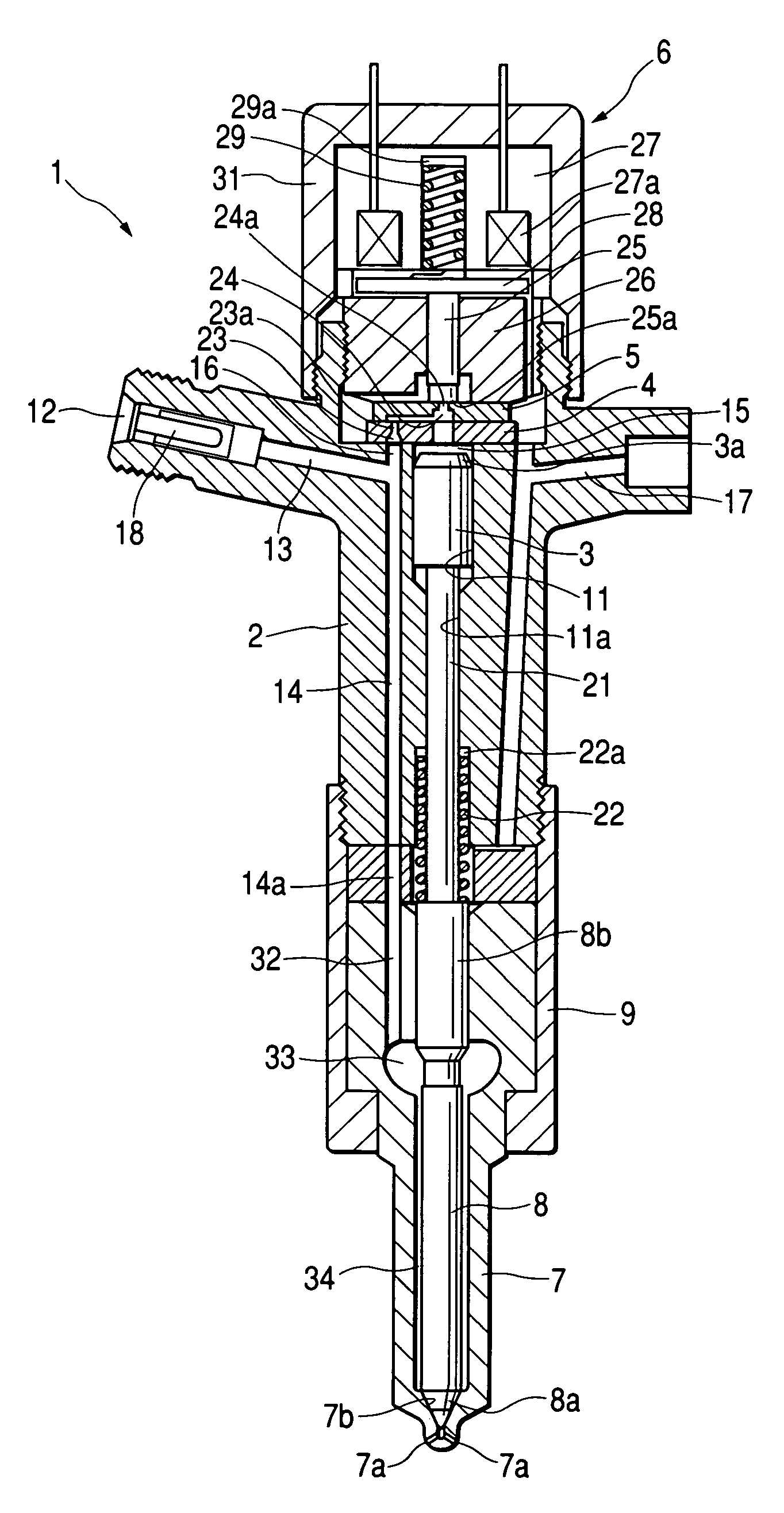
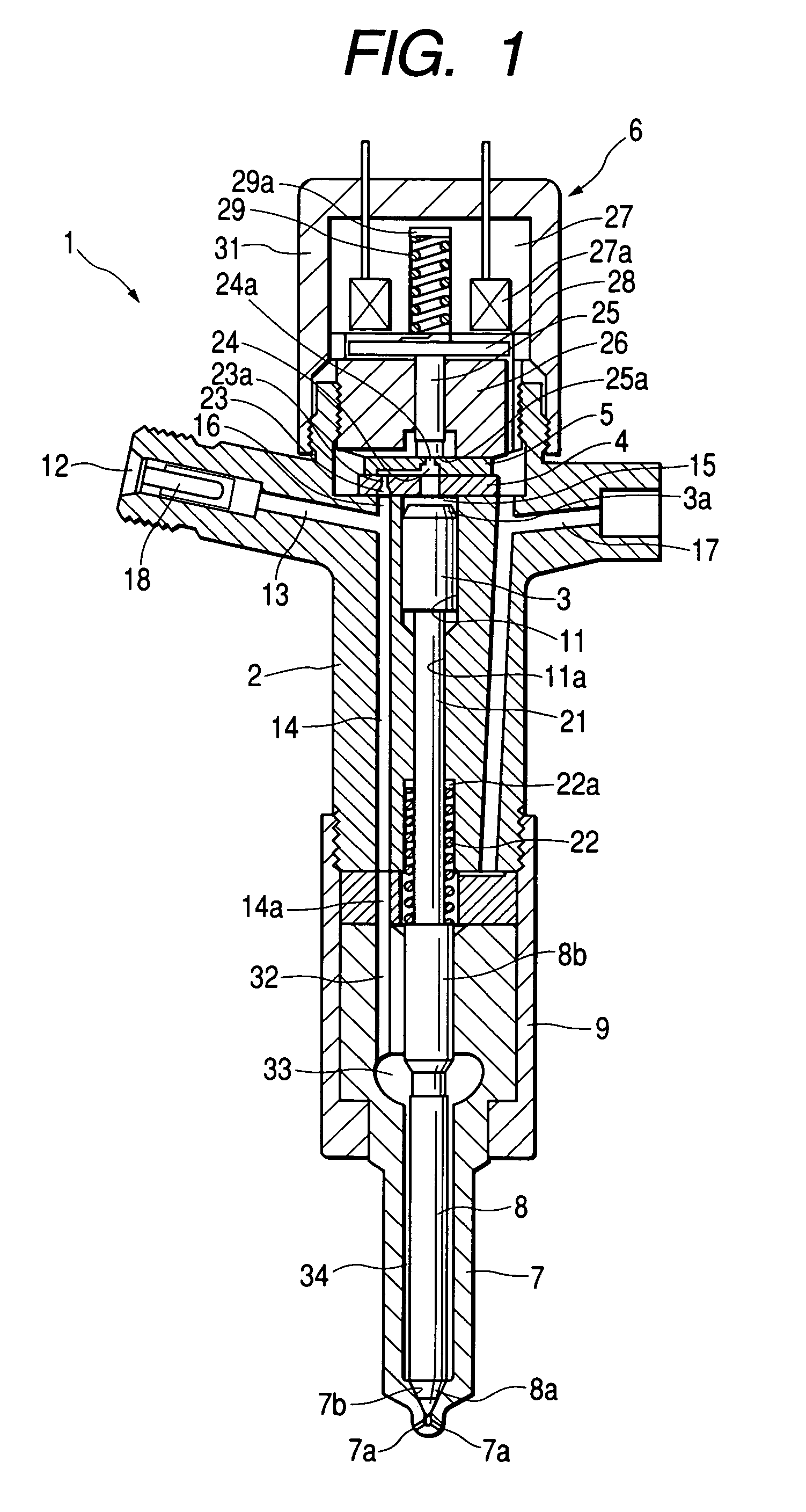
[0061]An injector 1 shown in FIG. 1 is, for example, incorporated into an accumulator fuel injection system for a diesel engine. The injector 1 receives pressurized fuel supplied from a common rail (not shown) and injects the pressurized fuel into an engine combustion chamber. The embodiment disclosed in FIG. 1 is a 2-way valve type injector.

Arrangement of Injector 1

[0062]First of all, the arrangement of the injector 1 will be explained.

[0063]The injector 1 includes a nozzle (described later), an injector body 2, a control piston 3, first and second passage members 4 and 5, and an electromagnetic valve 6.

[0064]The nozzle includes a nozzle body 7 having a nozzle hole 7a formed at its distal end and a needle valve 8 slidably coupled in an inside space of the nozzle body 7. The nozzle body 7 is fixed to the lower part of the inje...

modified embodiment

[0169]The above-described injector 1 is a mere example of this invention. The present invention can be applied to other injectors having different arrangements.

[0170]For example, in the case that the present invention is applied to the 2-way valve type injector 1 as shown in the above-descried embodiment, the first and second passage members 4 and 5 respectively having the inlet orifice 23a and the outlet orifice 24a can be integrated into a single orifice plate. In this manner, the practical structure or arrangement of the injector 1 can be modified in various ways.

[0171]Furthermore, although the above-described embodiment is based on the 2-way valve type injector 1, the present invention can be applied to various kinds of injectors including an injector 1 having a needle valve 8 being directly driven by a linear solenoid (e.g., a piezo-actuator)

[0172]Furthermore, application of the present invention is not limited to the assembling of the injectors. The present invention provides ...


PUM

PropertyMeasurementUnit
pressureaaaaaaaaaa
magnetic forceaaaaaaaaaa
volumeaaaaaaaaaa

Abstract

A constituent parts assembling method for an actuating apparatus includes a step of assigning ID classification to each of constituent parts with reference to characteristics difference of respective parts when these constituent parts give influence to output characteristics of an injector. In the processes of assembling these constituent parts, when a selected constituent part has a certain ID classification being assigned beforehand, this assembling method includes a step of executing constituent part selection in accordance with an instruction of constituent part designating means which designates other constituent part having an ID classification corresponding to the ID classification assigned to the selected constituent part, and also includes a step of assembling the selected constituent parts into the injector.

Description

BACKGROUND OF THE INVENTION[0001]The present invention relates to a constituent parts assembling method for an actuating apparatus which includes a plurality of constituent parts and produces an output in response to an input signal, and more particularly relates to a technique being preferably applicable to an actuating apparatus (e.g., an injector of a fuel injection apparatus) which includes numerous mechanical constituent parts and accordingly inherently possesses the output characteristics being not easily adjustable through electric adjustment only.[0002]One representative example of the actuating apparatuses including numerous mechanical constituent parts is an accumulator fuel injection system.[0003]For example, a well-known injector incorporated in an accumulator fuel injection system is a 2-way valve type which includes a control chamber provided at a non-injection side of a control piston accommodated in this injector and an electromagnetic valve for open / close controllin...

Claims


Application Information

Patent Timeline
Patent Type & Authority Patents(United States)
IPC IPC(8): F02D41/24F02M47/00F02M47/02F02M61/16F02M61/18F02M65/00
CPCF02M47/027F02M61/168F02M61/18F02M65/005F02M61/1806Y10T29/49405Y10T29/49231
Inventor YODA, TOSHIYUKISAKOU, TAKAHARU
Owner DENSO CORP
Why Eureka
Try Eureka