Osmotic implant with membrane and membrane retention means

a technology of implantable membrane and membrane plug, which is applied in the field of osmotic control implantable delivery devices, can solve the problems of increasing the cost and complexity of a high-pressure osmotic delivery system, the membrane plug itself is required to withstand the expansion of the osmotic engine, and the difficulty of manufacturing injection molded semi-permeable membranes without internals

Inactive Publication Date: 2007-01-16
INTARCIA THERAPEUTICS INC
View PDF24 Cites 137 Cited by
  • Summary
  • Abstract
  • Description
  • Claims
  • Application Information

AI Technical Summary

Benefits of technology

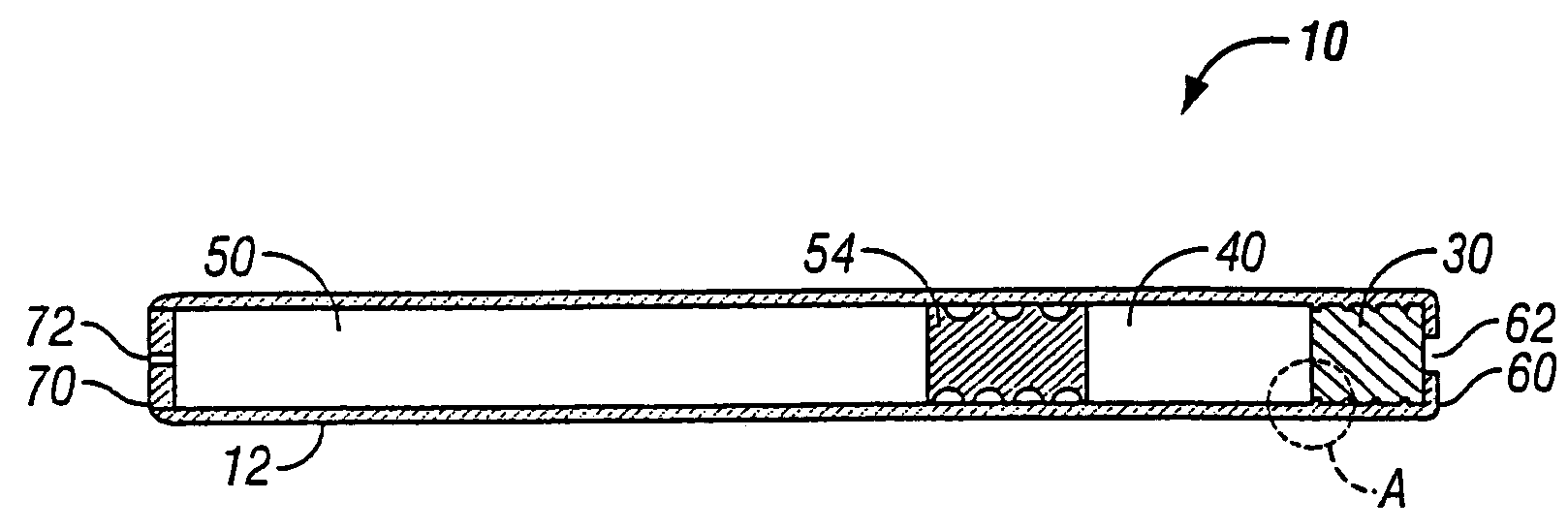
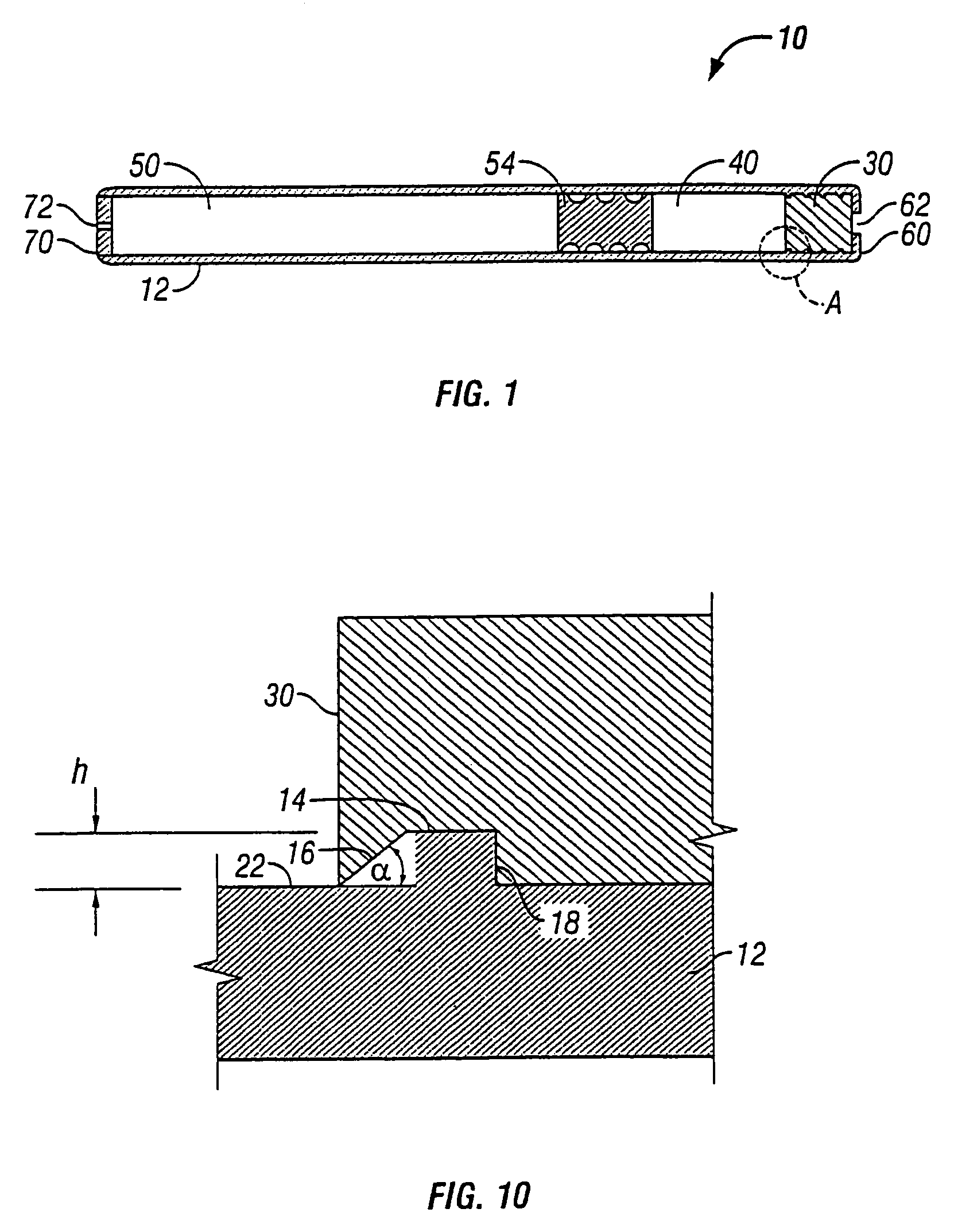
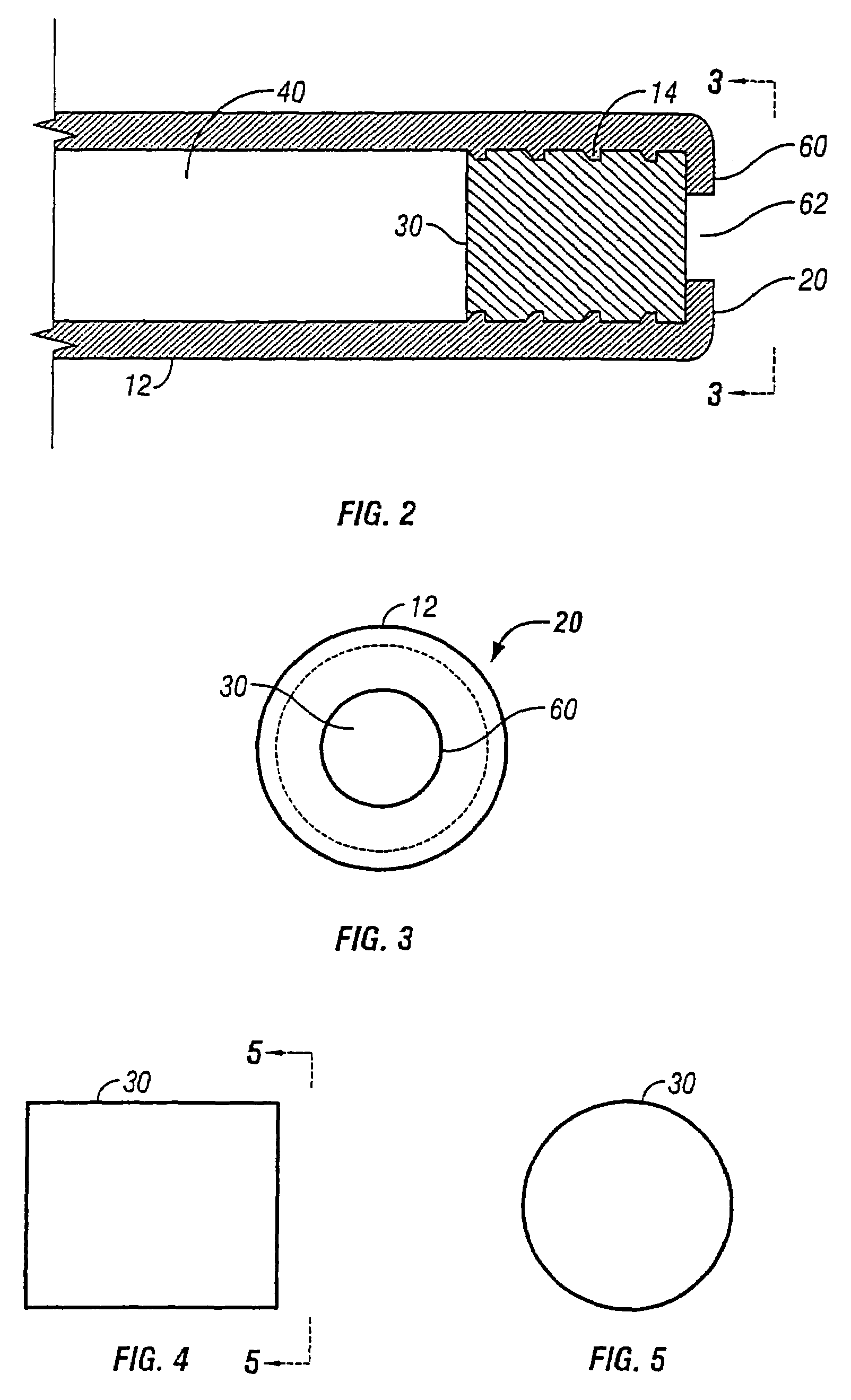
[0021]In a further aspect, the present invention pertains to an osmotic system for controlled delivery of a beneficial agent including an implantable capsule having a beneficial agent delivery end and a fluid uptake end. The capsule includes a beneficial agent reservoir positioned adjacent the beneficial agent delivery end for housing the beneficial agent. A piston is positioned between the beneficial agent reservoir and the fluid uptake end. An osmotic engine is positioned between the piston and the fluid uptake end. The osmotic engine is expandable at a controlled rate and when expanding, applies a pushing force against the piston which applies a pushing force against the beneficial agent, such that the beneficial agent is released through the beneficial agent delivery end at a predetermined rate. A membrane material is received in the fluid uptake end and provides a fluid permeable barrier between an interior and an exterior of the capsule. A membrane material-retaining means is positioned at the fluid uptake end, with the membrane material-retaining means including at least one opening for allowing passage of fluid. The membrane material-retaining means also prevents the

Problems solved by technology

Injection molded semipermeable membranes may be difficult to manufacture without internal stresses; thus performance may vary slightly from plug to plug.
An additional drawback of known osmotic delivery systems is th

Method used


Image

  • Osmotic implant with membrane and membrane retention means
  • Osmotic implant with membrane and membrane retention means
  • Osmotic implant with membrane and membrane retention means

Examples


Embodiment Construction

[0038]The present invention relates to an osmotic delivery system 10 having a membrane material 30 for controlling a delivery rate of a beneficial agent from the osmotic delivery system.

DEFINITIONS

[0039]The term “active agent” or “beneficial agent” intends the active agent(s) optionally in combination with pharmaceutically acceptable carriers and optionally additional ingredients such as antioxidants, stabilizing agents, permeation enhancers, etc.

[0040]The term “impermeable” intends that the material is sufficiently impermeable to environmental fluids as well as ingredients contained within the dispensing device such that the migration of such materials into or out of the device through the impermeable device is so low as to have substantially no adverse impact on the function of the device during the delivery period.

[0041]The term “semipermeable” intends that the material is permeable to external fluids but substantially impermeable to other ingredients contained within the dispen...


PUM


Abstract

An osmotic delivery system for controlled delivery of a beneficial agent includes an implantable capsule containing a beneficial agent and an osmotic engine that swells on contact with water, thereby causing the release of the beneficial agent over time. The osmotic delivery system has a membrane material that allows a controlled amount of fluid to enter from an exterior of the capsule, while preventing the compositions within the capsule from passing out of the capsule. The osmotic delivery system is designed to meet at least the operating pressures of 1000 psi. The membrane material is cast, calendered or extruded followed by machining (i.e., die-cutting, stamping or otherwise cutting to shape) to provide a uniform nonribbed membrane material. The capsule also includes a membrane material-retaining means that is positioned at a fluid uptake end to retain the membrane material within the capsule, even under periods of high pressure.

Description

[0001]This application claims the priority of U.S. Application Ser. No. 60 / 300,575 filed Jun. 22, 2001, which is incorporated herein by reference.BACKGROUND OF THE INVENTION[0002]1. Field of the Invention[0003]The present invention relates to osmotically controlled implantable delivery devices, and more particularly to a delivery system having a membrane material that controls the delivery rate of a beneficial agent from the delivery system, in which the membrane material is cast, calendered or extruded, then machined (i.e., stamped, die cut or otherwise cut to shape), and the membrane material is maintained within the delivery device by a retaining means.[0004]2. Description of the Related Art[0005]Controlled delivery of beneficial agents, such as drugs, in the medical and veterinary fields, has been accomplished by a variety of methods, including implantable delivery devices such as implantable osmotic delivery devices and implantable diffusion controlled delivery systems. Osmotic...

Claims


Application Information

Patent Timeline
IPC IPC(8): A61F13/00A61F2/00A61K9/48A61K9/00A61K9/22A61K9/52A61M37/00
CPCA61K9/0004
Inventor PEERY, JOHN R.GILBERT, SCOTT J.BROWN, JAMES E.
Owner INTARCIA THERAPEUTICS INC
Why Eureka
Try Eureka