Compact tunable antenna

a tunable antenna and compact technology, applied in the direction of loop antennas, resonant antennas, radiating element structural forms, etc., can solve the problems of antennas that do not provide a way to eliminate, and antennas that have significant drawbacks, etc., to achieve low-efficiency antennas and broad tuning bandwidth.

Inactive Publication Date: 2007-01-16
HRL LAB
View PDF188 Cites 90 Cited by
  • Summary
  • Abstract
  • Description
  • Claims
  • Application Information

AI Technical Summary

Benefits of technology

[0021]The presently disclosed technology provides an F type antenna that addresses the aforementioned needs. The antenna is much more compact than previous designs and has the ability to match the input impedance to a 50 ohm transmission line over a broad tuning bandwidth. This is primarily due to the simple resonant structure that provides the mode or modes of radiation. The tuning mechanism of the present invention is also compatible with MEMS switch devices. Previous switches were somewhat lossy, which results in a low-efficiency antenna. This effect is aggravated by high-Q antennas, and thus rules out tunable F-type antennas, which are typically high Q. The compact nature of the F-type antenna could allow it to be used in, for example, a handheld transceiver or for in-car communications with a PDA or telephone. Also, the ability to tune the resonant frequency would allow a single antenna to be installed in cars that are sold in different countries, since the antenna could simply be tuned to use the frequencies allocated for each service in each individual country. Other services that could benefit from such an antenna are AMPS, PCS, Bluetooth, 802.1 1a, or military bands.

Problems solved by technology

However, this antenna is extremely sensitive to the position of the bias circuits and does not have the ability to tune the polarization and the pattern.8. Jeffrey Herd, Marat Davidovitz, Hans Steyskal, “Reconfigurable Microstrip Array Geometry which Utilizes Microelectromechanical System MEMS switches”, U.S. Pat. No. 6,198,438 describes an array of patch antennas that are connected by RF MEMS switches.
However, this antenna requires a large number of switches and the antenna does not provide a way to eliminate the problem of interference between the DC feed lines and the RF part of the antenna.9. Gerard Hayes, Robert Sadler, “Convertible Loop / Inverted F Antennas and Wireless Communicators Incorporating the Same”, U.S. Pat. No. 6,204,819 describes an F-type antenna.
However, this antenna has significant drawbacks due to its complexity.
Furthermore, this antenna does not allow for angle diversity.10.
Previous switches were somewhat lossy, which results in a low-efficiency antenna.

Method used


Image

  • Compact tunable antenna
  • Compact tunable antenna
  • Compact tunable antenna

Examples


Embodiment Construction

[0040]This technology will now be described more fully hereinafter with reference to the accompanying drawings, in which preferred embodiments are shown. The presently described technology may be embodied in many different forms and should not be construed as limited to the embodiments set forth herein. Further, the dimensions of certain elements shown in the accompanying drawings may be exaggerated to more clearly show details. The present disclosure should not be construed as being limited to the dimensional relations shown in the drawings, nor should the individual elements shown in the drawings be construed to be limited to the dimensions shown.

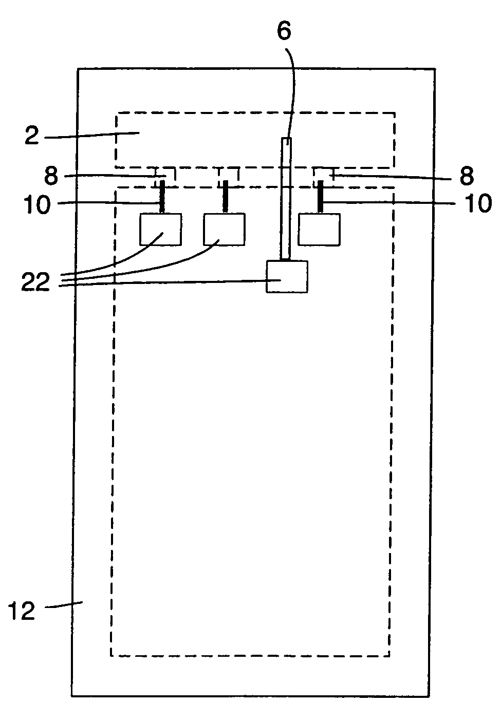
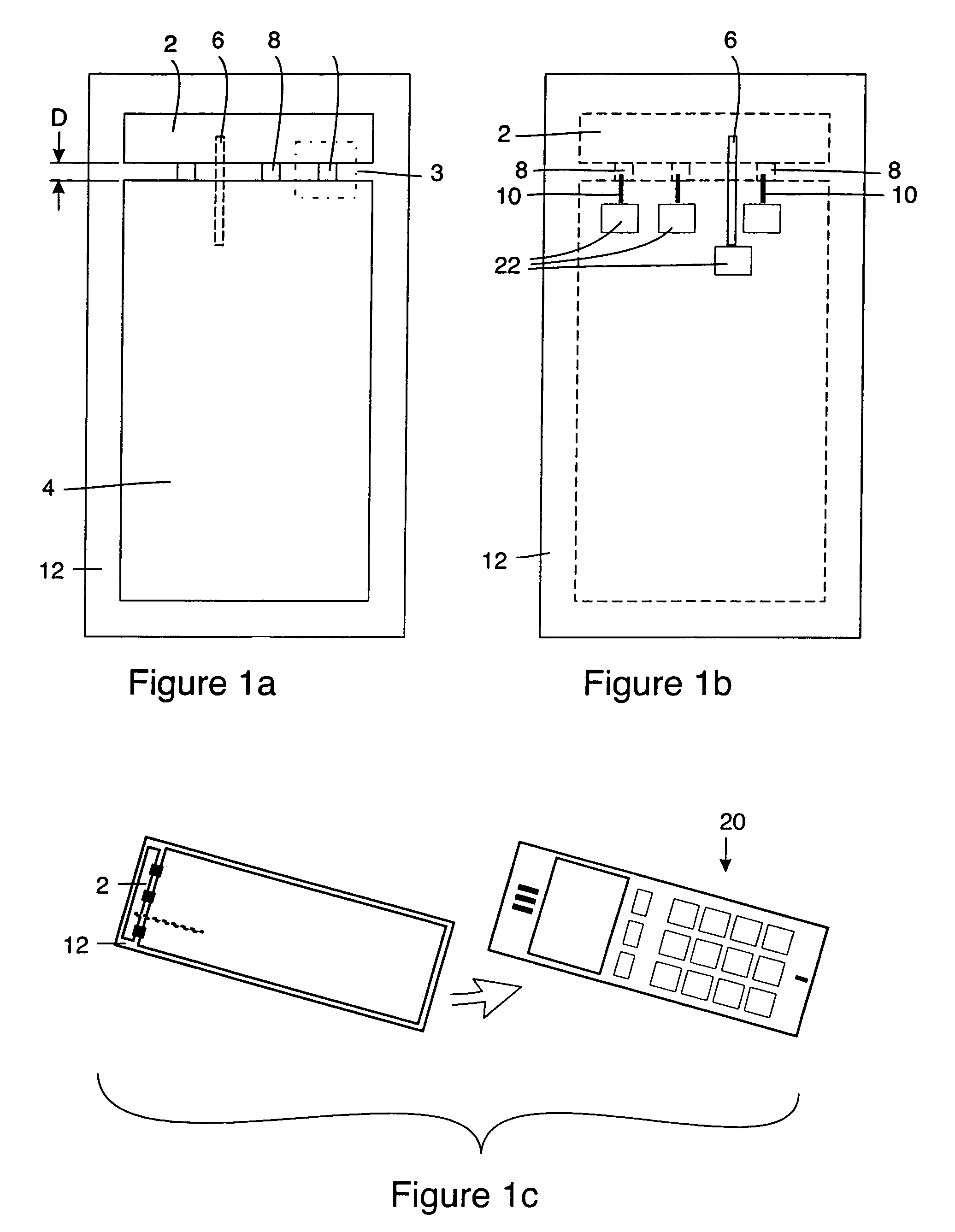
[0041]FIG. 1a depicts a front side view of an F antenna according to the present disclosure. The antenna, in its most basic form, comprises an electrically conductive tab 2, a conductive sheet or ground plane 4, a feed line 6, and switches 8. F antennas can be broadly characterized as typically having an antenna size between ¼–½ the wavel...


PUM


Abstract

The present disclosure relates to a method and an antenna for transmitting/receiving a RF signal at a plurality of different frequencies. Transmitting/receiving a RF signal at a plurality of different frequencies is achieved by providing a F antenna comprising a plurality of switches which can be used to adjust the resonant frequency of the antenna. By providing a F antenna, the antenna will be much smaller than the wavelength at which the antenna is operating. This allows the antenna to be used in compact devices such as PDA's and cellular phones.

Description

CROSS REFERENCE TO RELATED APPLICATIONS[0001]This application claims the benefit of U.S. Provisional Patent Application No. 60 / 470,025 filed May 12, 2003, the disclosure of which is hereby incorporated herein by reference.[0002]The present document is related to the co-pending and commonly assigned patent application documents entitled “RF MEMS Switch With Integrated Impedance Matching Structure” U.S. Patent Application No. 60 / 470,026 filed on May 12, 2003, and “RF MEMS-Tuned Slot Antenna and a Method of Making Same”, U.S. Patent Application No. 60 / 343,888 filed Dec. 27, 2001 and its related non-provisional application U.S. patent application Ser. No. 10 / 192,986, which claims priority to U.S. Ser. No. 60 / 343,888. The contents of these related applications are hereby incorporated by reference herein.[0003]1. Technical Field[0004]The technical field of this disclosure relates to tunable antennas and more specifically, a compact tunable F antenna.BACKGROUND[0005]Antennas that rely on t...

Claims


Application Information

Patent Timeline
Patent Type & Authority Patents(United States)
IPC IPC(8): H01Q1/24H01Q3/24H01Q9/04
CPCH01Q1/243H01Q3/247H01Q9/14H01Q9/0442H01Q9/0421
Inventor SIEVENPIPER, DANIEL F.
Owner HRL LAB
Why Eureka
Try Eureka