Wavelength converting devices

a technology of converting devices and wavelengths, applied in the direction of instruments, light demodulation, non-linear optics, etc., can solve the problems of fluctuation and instability of the output of blue light from the device, and achieve the effects of improving the thermal uniformity and stability of light in the direction of the guiding wave, facilitating the handling of the device, and improving the strength of the devi

Active Publication Date: 2007-01-16
NGK INSULATORS LTD
View PDF16 Cites 3 Cited by
  • Summary
  • Abstract
  • Description
  • Claims
  • Application Information

AI Technical Summary

Benefits of technology

[0016]The present inventors have tried to join a supporting body with the main face of a wavelength converting layer made of a plate of a non-linear optical crystal, based on the discovery of the cycles of the output power of the converted light described above. The inventors thus have found that the thermal uniformity and stability of light in the direction of the guiding wave can be improved to stabilize the output power of the converted light. The present invention is based on the discovery.
[0017]The following additional effect can be obtained. That is, a plate of a non-linear optical crystal is joined with a supporting body to fabricate a wavelength converting device, so that the strength of the device is improved and the handling of the device is facilitated.

Problems solved by technology

It is considered that the cycles are repeated in the device so that the output of the blue light from the device is fluctuated and unstable.

Method used


Image

  • Wavelength converting devices
  • Wavelength converting devices

Examples


example 1

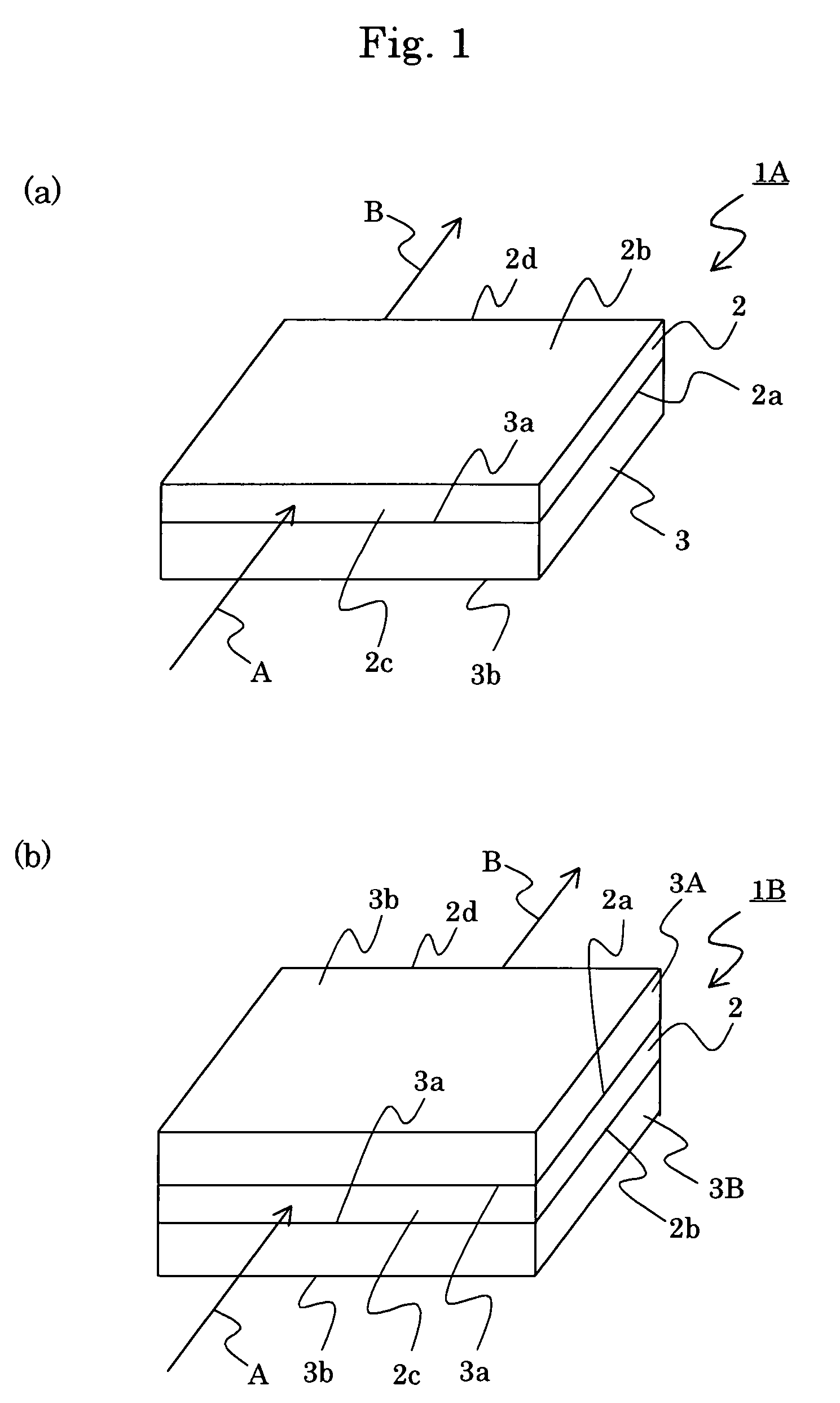
[0040]A plate-shaped body 2 made of potassium lithium niobate, of Z-cut and having a length of 15 mm and width of 15 mm and thickness of 0.5 mm was prepared. The plate-shaped body was prepared by means of micro pull-down method. A supporting body 3 made of soda glass and having a length of 20 mm, a width of 20 mm and thickness of 1 mm was prepared. The joining faces of the substrate 2 and supporting body 3 were subjected to chemical machinery polishing to improve the flatness to a value of 0.5 μm or lower. An adhesive of thermosetting type was used to join them at 150° C. to obtain a joined sample “A.” The thickness of the adhesive layer between the substrate 2 and supporting body 3 was about 0.5 μm. The thus obtained joined sample “A” was cut by a dicer to obtain a chip having a length of 3.5 mm. Both end faces of the chip were subjected to optical polishing. The resulting chip was further cut with a dicer to obtain a device 1A having a width of 2 mm, a thickness of 1.5 mm and a le...

example 2

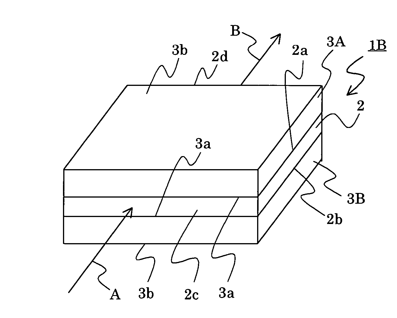
[0042]The joined sample “A” described in the example 1 was polished at another main face 2b (not joined) of the substrate 2 to obtain a joined sample “B” having a thickness of 1.3 mm. To the main face 2b (not joined) of the joined sample “B,” a soda glass substrate 3B having a length of 20 mm, a width of 20 mm and a thickness of 1.2 mm was adhered using a ultraviolet light curable resin to obtain a device 1B having a thickness of 2.5 mm. The thickness of the adhesive layer of the ultraviolet light curable resin was about 5 μm. The device 1B was used to perform an experiment of wavelength conversion according to the same procedure as Example 1. As a result, even when the average output of the fundamental light source was elevated to 10 W, fluctuation of the output power of the harmonic wave with blue light (wavelength of 457 nm) was not observed and the device oscillated with stability.

example 3

[0043]Devices were produced according to the same procedure as Example 1, except that the refractive indices of potassium lithium niobate crystal forming the plate-shaped body 2 so that the resulting devices can attain phase matching at −40, 0, 60, 100, 150 and 200° C., respectively, at a wavelength of 914 nm. The devices were held at the respective phase matching temperatures to perform experiments of wavelength conversion according to the same procedure as Example 1. As a result, even when the average output of the fundamental light source was elevated to 3 W, fluctuation of the output power of the harmonic wave with blue light (wavelength of 457 nm) was not observed and the device oscillated with stability.


PUM

PropertyMeasurementUnit
thermal conductivityaaaaaaaaaa
absorption coefficientaaaaaaaaaa
wavelengthaaaaaaaaaa

Abstract

Wavelength conversion devices for converting fundamental waves to light of a different wavelength are provided. The devices have a wavelength converting layer comprising a plate-shaped body of a non-linear optical crystal having a first main face and a second main face. A supporting body is joined with the first main face of the wavelength converting layer. An additional supporting body may also be joined with the second main face of the wavelength converting layer.

Description

CROSS REFERENCE TO RELATED APPLICATIONS[0001]This application is a continuation of International Application No. PCT / JP2004 / 002965, having an international filing date of Mar. 8, 2004, which designated the United States, the entirety of which is incorporated herein by reference.[0002]This application also claims the benefit of Japanese Application No. 2003-064437, filed Mar. 11, 2003, and Japanese Application No. 2004-029546, filed Feb. 5, 2004, the entireties of which are incorporated herein by reference.BACKGROUND OF THE INVENTION[0003]1. Field of the Invention[0004]The present invention relates to a wavelength converting device suitable for a blue light source device or the like.[0005]2. Related Art Statement[0006]A second harmonic wave generating device with reduced optical damage and without the necessity of quasi-phase matching and a high precision control of domains was proposed in Japanese patent publication 8-339, 002A. According to the publication, it is produced a substra...

Claims


Application Information

Patent Timeline
Patent Type & Authority Patents(United States)
IPC IPC(8): G02F1/355G02F1/35G02F1/37
CPCG02F1/3551G02F2203/60G02F2001/3505G02F1/377G02F1/3505
Inventor NODA, KEN-ICHIIWAI, MAKOTOYOSHINO, TAKASHI
Owner NGK INSULATORS LTD
Why Eureka
Try Eureka