
Substrate-coating system and an associated substrate-heating method

a substrate heating and substrate technology, applied in the field of substrate heating systems, can solve the problems of long heating period, ineffective use of thermal radiators to heat such substrates, and high so as to avoid excessive mechanical stress of substrates and heat up much faster

Active Publication Date: 2007-01-23
CARL ZEISS SMT GMBH
View PDF21 Cites 11 Cited by
  • Summary
  • Abstract
  • Description
  • Claims
  • Application Information

AI Technical Summary

Benefits of technology

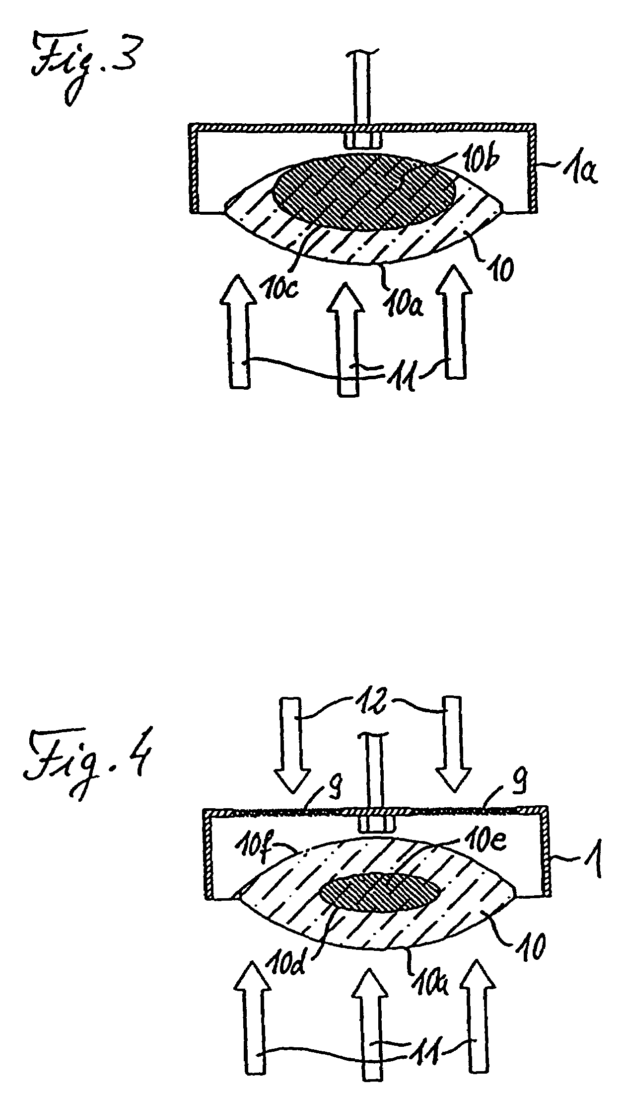
[0011]In the case of the substrate-coating system according to the invention, its substrate heater includes a backside heater for actively heating the substrates from their backside, i.e., their side opposite the side to be coated, while they are at their respective coating positions. Since no space on this substrate side opposite that to be coated need be left unobstructed for the transport of coating material from a coating source to the substrate, there is more freedom for designing and laying out the backside heater than in the case of front-side heaters, i.e. heaters that face the side to be coated. In particular, the backside heater may be positioned relatively close to the substrates and have a shape that is adapted to optimally suit the application involved. For otherwise identical conditions, the heater power transferable to the substrates increases with the inverse square of the distance between heater and substrate. All considered the backside heating thus provides highly effective, uniform, gentle substrate heating.
[0022]Both types of heating thus reliably avoid occurrences of excessive mechanical stressing of substrates, even in cases where the heat-conducting element or substrate-carrier fixture has higher absorption for the short-wavelength portion of the thermal radiation involved and thus heat up much more rapidly than the substrate.

Problems solved by technology

However, this type of thermal-radiation heating of substrates presents problems if the substrate material only weakly absorbs in that wavelength range, which is particularly true for calcium-fluoride (CaF2) substrates, and thus also for commonly employed optical components, such as lenses, fabricated from that material.
Employing IR thermal radiators to heat such substrates is particularly ineffective and involves long heating periods if the thermal radiators are arranged at a relatively large distance from that side of the substrates that is to be coated in order not to shield that side of the substrates and thereby interfere with the transport of coating material from a coating source to that side of the substrates.
Another problem that occurs in the case of CaF2-substrates is the comparatively large coefficient of thermal expansion of CaF2, which requires carrying out heating and cooling-down cycles sufficiently gently that cracking due to thermally induced mechanical stresses will be avoided.
The heating chamber, which is specifically designed for thermally conditioning substrates, in particular, flat glass substrates, is not suited to simultaneously serving as the chamber to be employed for the subsequent surface treatment of substrates, such as coating substrates, due to its design.

Method used


Image

  • Substrate-coating system and an associated substrate-heating method
  • Substrate-coating system and an associated substrate-heating method
  • Substrate-coating system and an associated substrate-heating method

Examples


Embodiment Construction

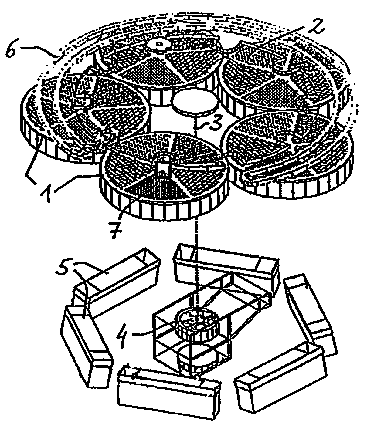
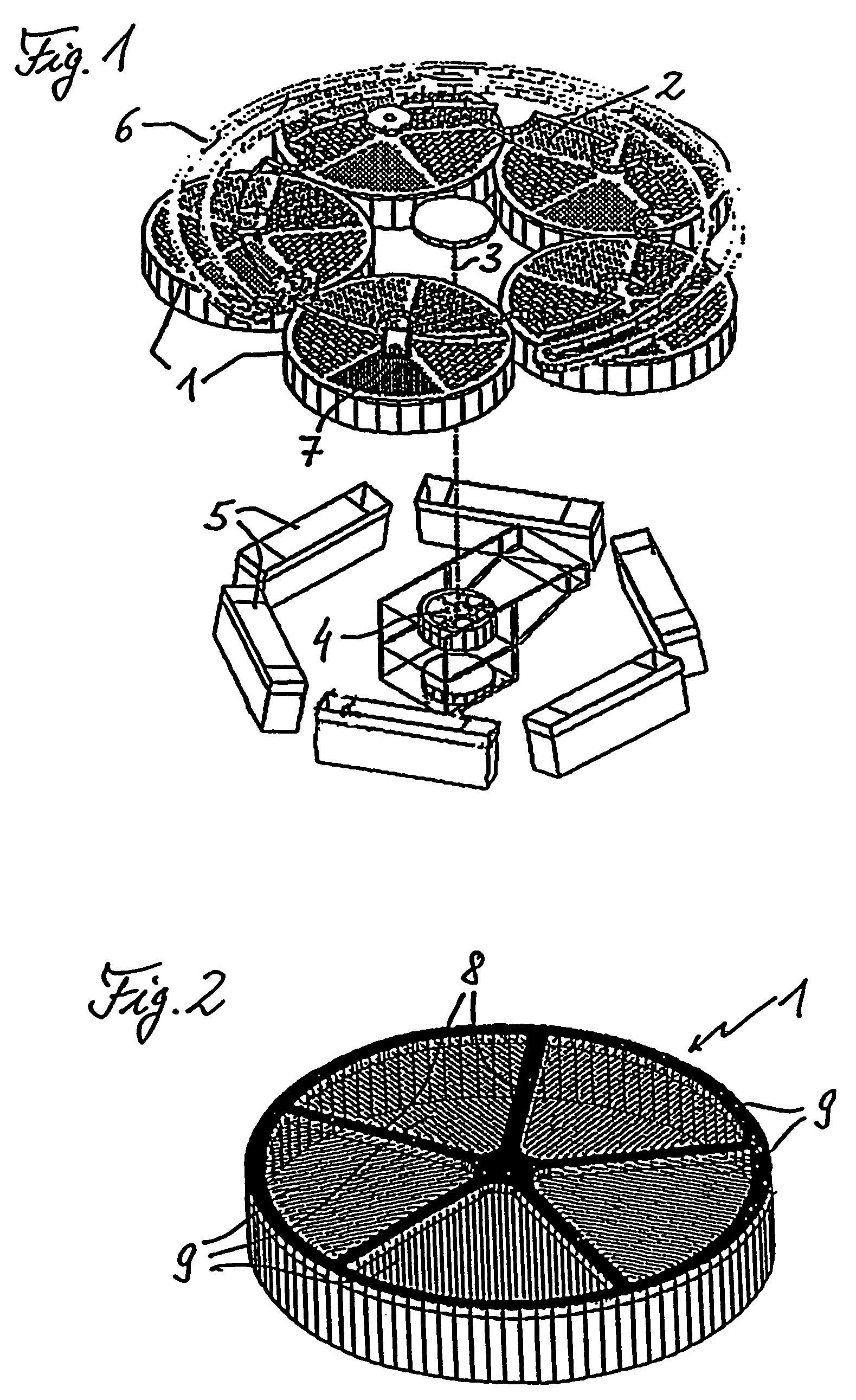
[0028]FIG. 1 depicts, in accordance with the invention, a part of a substrate-coating system with which optical components, as well as other types of substrates, may be coated in desired manners. For example, desired coatings, such as multilayer stacks of oxides and fluorides having suitable film thicknesses, may be deposited on, e.g., lenses and other types of optical components, by evaporation at suitable substrate temperatures in order to obtain coatings complying with prescribed sets of specifications regarding their optical properties, environmental aspects, resistance to radiation damage, adhesion to substrates, and resistance to chemical attack.

[0029]In particular, that part thereof depicted in FIG. 1 has a conventional so-called planetary system, upon which five circular, pan-shaped, substrate carriers 1 whose open ends face downward, each of which has an evaporation ring 18 as a substrate-carrier fixture, are mounted in a conventional manner, which has not been depicted in ...


PUM

PropertyMeasurementUnit
IR wavelength rangeaaaaaaaaaa

Abstract

A substrate-coating system and an associated substrate-heating method, wherein the substrate-coating system is equipped with a substrate holder (1, 2) for holding at least one substrate at a coating position where it is coated on a coating side, and with a substrate heater (5, 6). The method includes heating at least one substrate that has been brought into such a system while it is being coated. The substrate heater includes a backside heater (6) for actively heating the substrate from its backside, i.e., that side opposite the side to be coated, while it is at its coating position. A heat-conducting element that is brought into thermal contact with a surface of the substrate may also be provided. Heater power is then regulated, based on the difference between the actual substrate temperature and a preset, desired, substrate temperature, and thereby limited such that the temperature of the heat-conducting element will not excessively increase over that of the substrate. The system and method are particularly applicable, e.g., to coating optical components fabricated from CaF2.

Description

[0001]This is a Continuation of application Ser. No. 10 / 687,870 filed Oct. 20, 2003 now abandoned, and which is hereby incorporated by reference. The disclosure is based also on U.S. Provisional application No. 60 / 419,095, filed Oct. 18, 2002.FIELD OF AND BACKGROUND OF THE INVENTION[0002]The invention relates to a substrate-coating system equipped with a substrate holder for holding at least one substrate at a coating position where it is coated on a coating side, a substrate heater, and a method for heating that at least one substrate during coating.[0003]Substrate coating systems of that type are generally known and are used for, for example, depositing functional and / or protective coatings on optical components. Heating substrates during coating will frequently allow improving the properties of the coatings deposited. In the case of optical coatings, substrate temperatures of, e.g., about 300° C., are typical.[0004]IR thermal radiators whose peak emission wavelengths range from 2...

Claims


Application Information

Patent Timeline
Patent Type & Authority Patents(United States)
IPC IPC(8): C23C14/00
CPCC23C14/541
Inventor HELLER, MATTHIASHSU, GEAN JACKMICHEL, FRANK
Owner CARL ZEISS SMT GMBH
Learn More