
Magnetic disk and method of producing the same

a magnetic disk and magnetic head technology, applied in the field of magnetic disks, can solve the problems of corrosion defect of the read/write element of the magnetic head, easy occurrence of the fly stiction defect in the lul system, and inability to obtain cleaning function, etc., and achieve excellent lul durability.

Active Publication Date: 2007-01-23
WESTERN DIGITAL TECH INC
View PDF9 Cites 74 Cited by
  • Summary
  • Abstract
  • Description
  • Claims
  • Application Information

AI Technical Summary

Benefits of technology

[0012]It is therefore an object of this invention to provide a magnetic disk which is capable of preventing occurrence of a fly stiction defect and has excellent LUL durability suitable for a LUL system and to provide a method of producing the same.
[0013]It is another object of this invention to provide a magnetic head which is capable of preventing occurrence of a fly stiction defect and is suitable for a lower flying height of a magnetic head and to provide a method of producing the same.

Problems solved by technology

As a result, it has been revealed that easy occurrence of the fly stiction defect in the LUL system is caused by contamination deposited on a surface of a magnetic head.
On the other hand, in the LUL system, such cleaning function is not obtained because the magnetic head does not slides on the magnetic disk in contact therewith.
The contamination migrating to and deposited on the surface of the magnetic head as mentioned above brings about a corrosion defect of a read / write element of the magnetic head.
Upon occurrence of corrosion of a read element portion of the head, an output power of a read signal is decreased to cause frequent occurrence of a read error.
Sometimes, a reading operation is impossible.
Further, a flying position of the magnetic head is disturbed by deposition of contamination.
This may brings about occurrence of a fly stiction defect in which the magnetic head suddenly falls onto the magnetic disk during operation of a magnetic disk apparatus.

Method used


Image

  • Magnetic disk and method of producing the same
  • Magnetic disk and method of producing the same

Examples


example 1

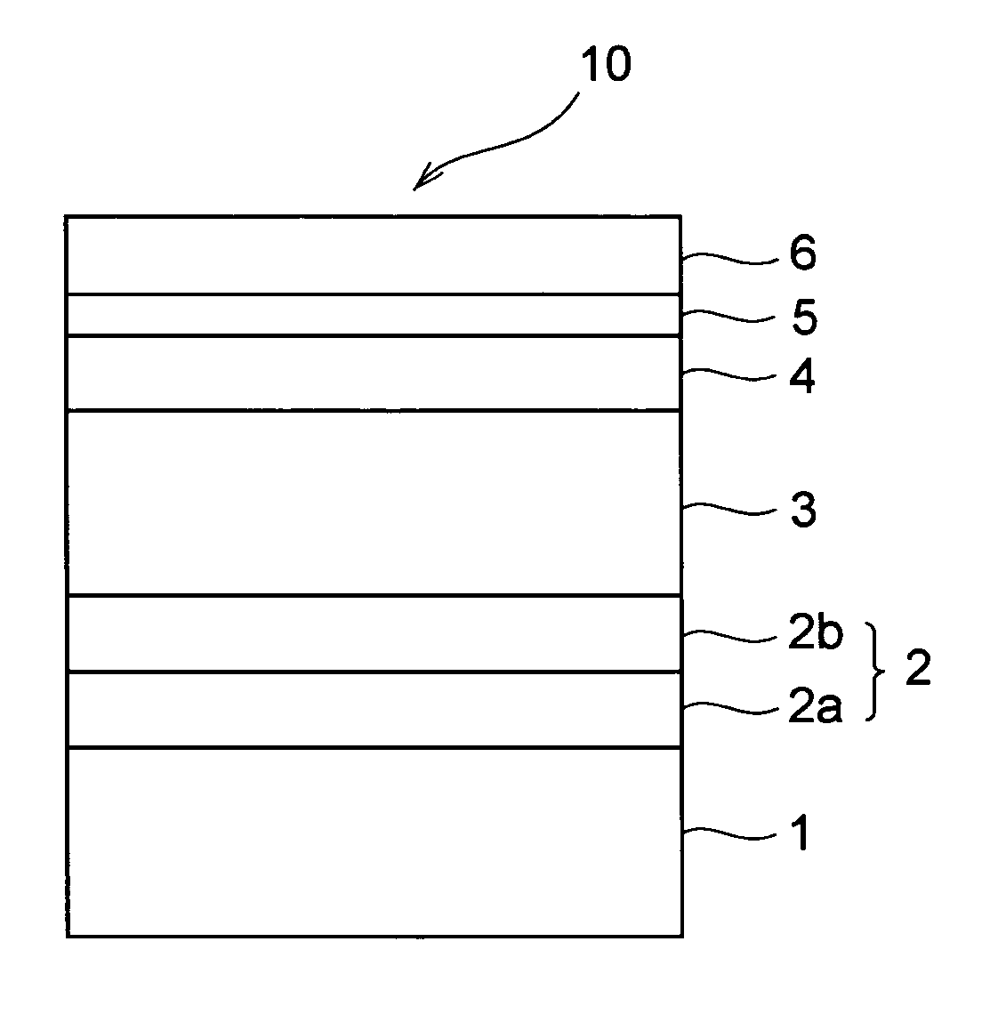
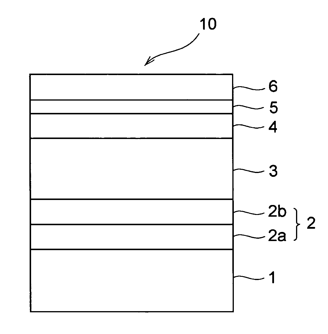
[0086]Referring to the sole FIGURE, a magnetic disk 10 in Example 1 comprises a glass substrate 1 with a nonmagnetic metal layer 2 composed of a seed layer 2a and an underlayer 2b, a magnetic layer 3, a carbon-based protection layer 4, an alcohol-based coupling layer 5, and a lubrication layer 6 successively laminated on the glass substrate 1. Each of these layers except the magnetic layer 3 is a nonmagnetic layer. FIGURE 1 shows a state immediately after deposition. A boundary between he alcohol-based coupling layer 5 and the lubrication layer 6 may become unclear with lapse of time because of mutual diffusion.

[0087]Next, description will be made of a method of producing the magnetic disk 10 in Example 1.

[0088]At first, a molten glass was subjected to direct pressing by the use of an upper die, a lower die, and a body die to obtain a disk-shaped glass plate made of an aluminosilicate glass and having a diameter of 66 mmφ and a thickness of 1.5 mm. The glass plate was subjected to g...

example 2

[0115]A magnetic disk in Example 2 was produced in the manner similar to the magnetic disk in Example 1 except that the alcohol-based coupling layer had a thickness of 1.5 Å.

[0116]The magnetic disk obtained in Example 2 had a surface roughness and a glide height equivalent to those of the magnetic disk in Example 1.

[0117]The magnetic disk in Example 2 was subjected to various performance tests in the manner similar to Example 1. The results are shown in Table 1.

example 3

[0118]A magnetic disk in Example 3 was produced in the manner similar to the magnetic disk in Example 1 except that the alcohol-based coupling layer had a thickness of 2.0 Å.

[0119]The magnetic disk obtained in Example 3 had a surface roughness and a glide height equivalent to those of the magnetic disk in Example 1.

[0120]The magnetic disk in Example 3 was subjected to various performance tests in the manner similar to Example 1. The results are shown in Table 1.


PUM

PropertyMeasurementUnit
water contact angleaaaaaaaaaa
thicknessaaaaaaaaaa
thicknessaaaaaaaaaa

Abstract

A magnetic disk includes a substrate on which a nonmagnetic metal layer, a magnetic layer, a carbon-based protection layer, an alcohol-based coupling layer, and a lubrication layer successively formed thereon. The lubrication layer contains a hydroxyl- or a carboxyl-modified compound as a lubricating material. The alcohol-based coupling layer contains, for example, lower alcohol as a main component and is deposited on the carbon-based protection layer, for example, by vapor deposition. The alcohol-based coupling layer may be replaced by a layer containing lower alcohol. The carbon-based protection layer may be deposited by plasma CVD.

Description

[0001]This application claims priority to Japanese patent application No. 2003-150860, the disclosure of which is incorporated herein by reference.BACKGROUND OF THE INVENTION[0002]This invention relates to a magnetic disk to be loaded in a magnetic disk apparatus, such as a HDD (hard disk drive), for recording information and a method of producing the same.[0003]At present, following the development of the IT (information technology) industry, it is requested to achieve dramatic technical innovation in the information recording technology, in particular, the magnetic recording technology. For example, in the field of a magnetic disk to be loaded in a magnetic disk apparatus, such as a HDD, there is a demand for a technique capable of achieving an information recording density on the order of 40 Gbit / inch2 to 100 Gbit / inch2 or more.[0004]In the magnetic disk apparatus, use has been made of a CSS (Contact Start and Stop) system. In the CSS system, a magnetic head is kept in contact wi...

Claims


Application Information

Patent Timeline
Patent Type & Authority Patents(United States)
IPC IPC(8): B05D5/12G11B5/72G11B5/84
CPCG11B5/72G11B5/8408G11B5/725G11B5/7268G11B5/7266
Inventor ISHIYAMA, MASAFUMI
Owner WESTERN DIGITAL TECH INC
Learn More