Liquid crystal display device

a liquid crystal display and display device technology, applied in non-linear optics, instruments, optics, etc., can solve the problems of reducing the visibility of the lcd device, the optical reflectivity of the other surface thereof, the opposite of the transparent substrate, still generally too large, etc., and achieve the effect of low reflectivity

Inactive Publication Date: 2007-01-23
INNOLUX CORP
View PDF8 Cites 14 Cited by
  • Summary
  • Abstract
  • Description
  • Claims
  • Application Information

AI Technical Summary

Benefits of technology

[0012]A main object of the present invention is to provide a col

Problems solved by technology

However, the black matrix 13 is conventionally made from a metal whose optical reflectivity is too high, or is made from a resin whose OD value is too low.
However, the optical reflecti

Method used


Image

  • Liquid crystal display device
  • Liquid crystal display device
  • Liquid crystal display device

Examples


Embodiment Construction

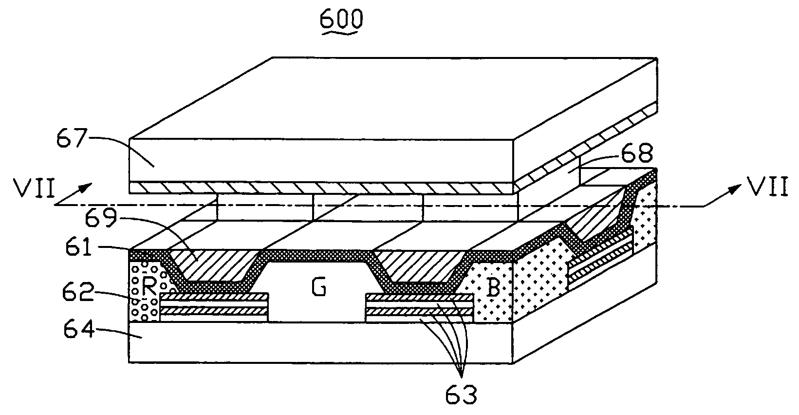
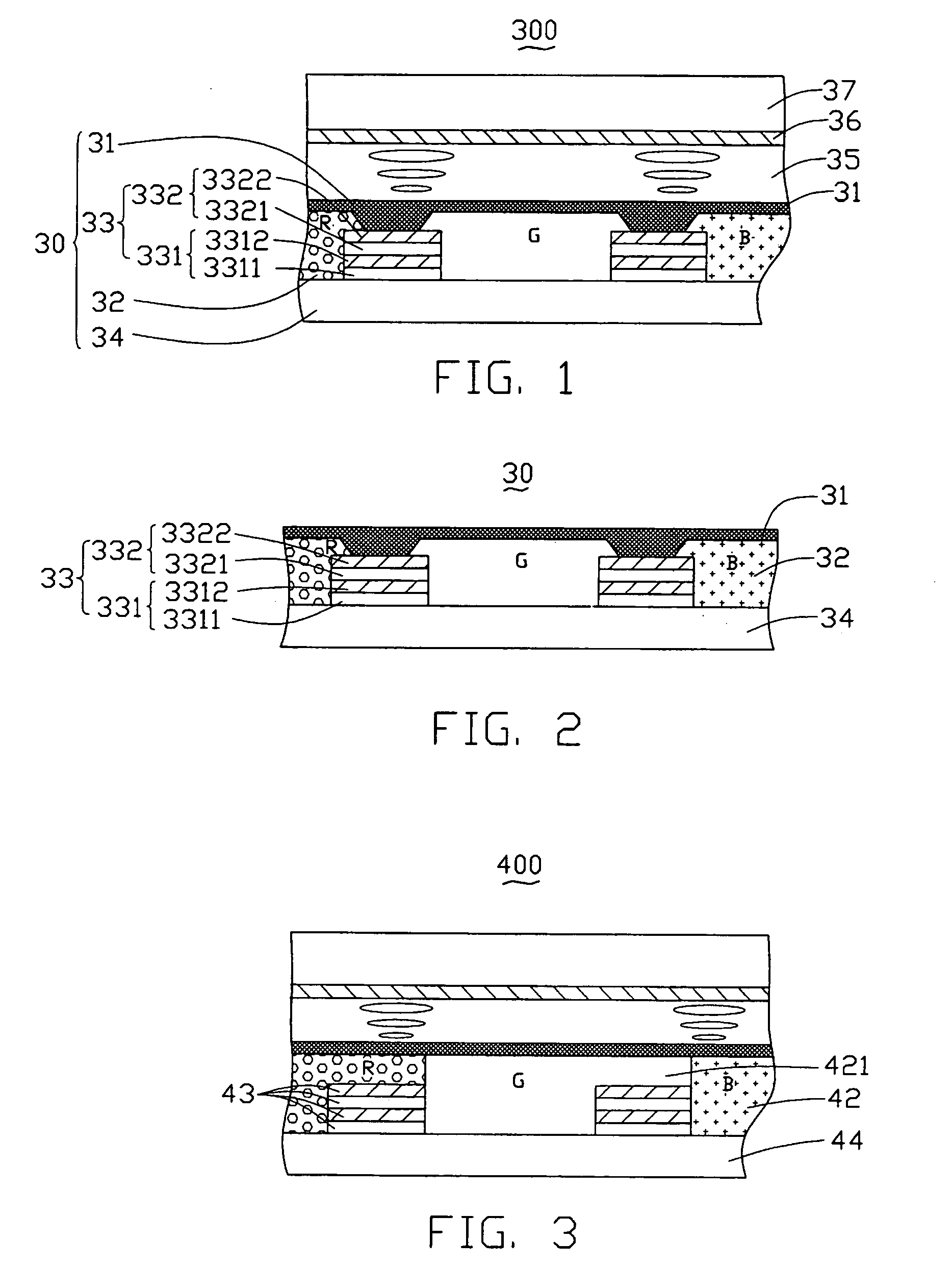
[0025]Referring to FIG. 1, an LCD device 300 in accordance with the first embodiment of the present invention is illustrated. The LCD device 300 includes a substrate-like color filter 30 and an opposing electrode substrate 37. The two substrates 30, 37 form a chamber therebetween filled with a liquid crystal layer 35.

[0026]The color filter 30 includes a transparent substrate 34, and a color resin layer 32 and a black matrix 33 formed on the transparent substrate 34. The black matrix 33 defines a plurality of apertures (not labeled) arranged in an array, the apertures being filled with the color resin layer 32 thus forming a plurality of color cells. In addition, an ITO layer 31 is formed on the color resin layer 32 and the black matrix 33. A TFT (Thin Film Transistor) layer 36 is formed on an inner surface (not labeled) of the electrode substrate 37.

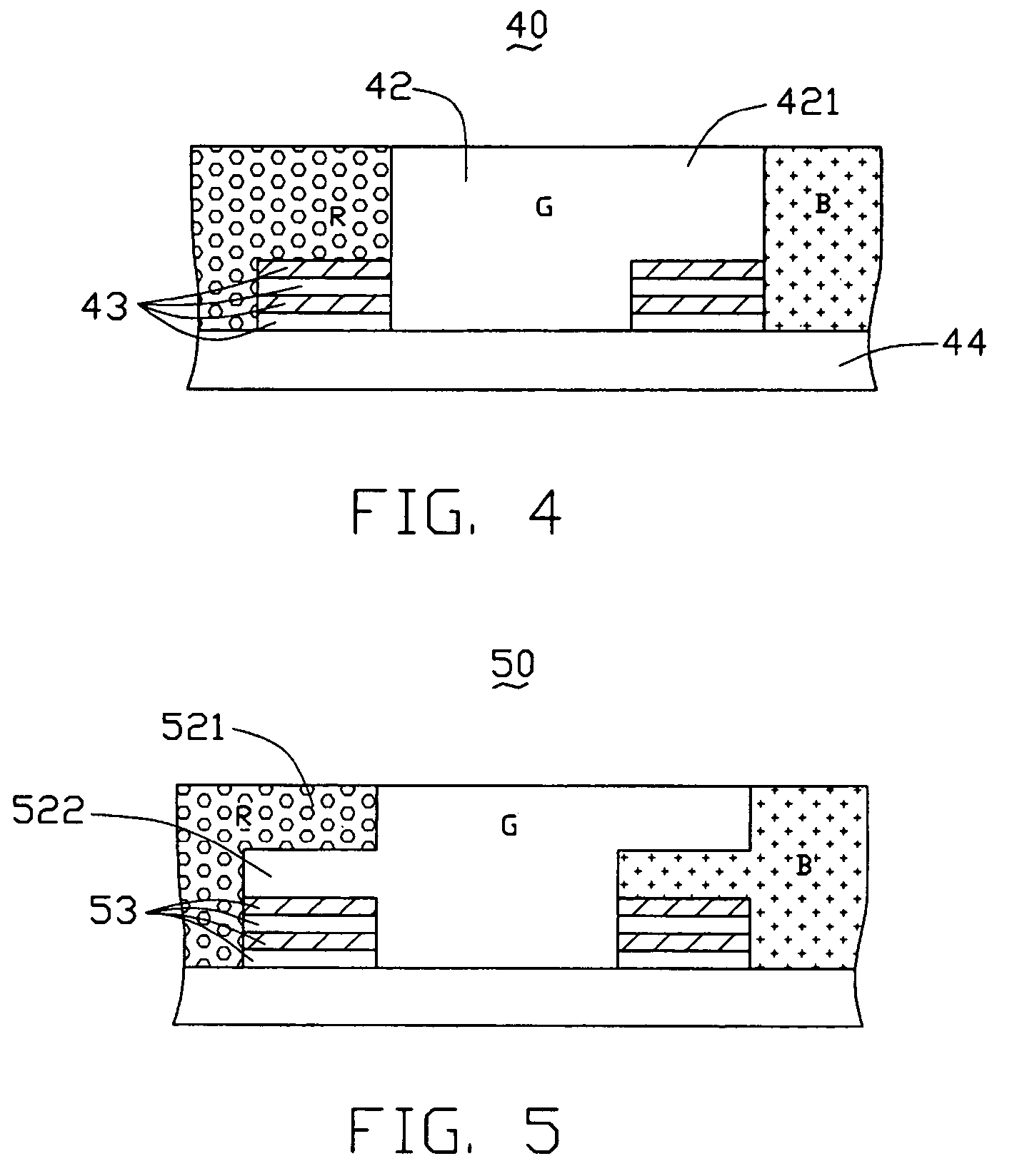
[0027]Referring to FIG 2, the black matrix 33 comprises two laminated antireflection layers 331, 332 formed on the transparent substrat...


PUM


Abstract

A color filter (30) includes a black matrix (33), and the black matrix has a first antireflection layer (331) and a second antireflection layer (332) on the first antireflection layer. Each antireflection layer includes a first antireflection film (3311, 3321) having a first refraction index, and a second antireflection film (3312, 3322) having a second refraction index which is different to the first refraction index. Because of so-called destructive interference of outside source light beams reflected from various interfaces defined by the first and second antireflection films, net reflection of the light beams by the black matrix back to an outside of the color filter is minimal. For similar reasons, net reflection of internal source light beams by the black matrix back to an inside of the color filter is minimal. As a result, visibility of a liquid crystal display device (300) employing the color filter is improved.

Description

BACKGROUND OF THE INVENTION[0001]1. Field of the Invention[0002]The invention generally relates to color filters having black matrixes, and to associated liquid crystal display (LCD) devices.[0003]2. The Prior Art[0004]In general, a monochrome or a color LCD device has the advantages of thinness, light weight and low power consumption. For this reason, LCD devices are widely used in various types of electronic equipment, from pocket calculators to large-scale office automation equipment.[0005]Conventionally, a color LCD device includes a color filter at a position opposite to a liquid crystal layer. The color filter has three kinds of color (red, green and blue—RGB) resins separated by a black matrix having a plurality of apertures. The visibility of the LCD device mainly depends upon the characteristics of the black matrix of the color filter.[0006]The basic structure of a conventional color LCD device is shown in FIG. 8. The LCD device 100 includes two glass substrates 14, 17 whic...

Claims


Application Information

Patent Timeline
IPC IPC(8): G02F1/1337G02F1/1335
CPCG02F1/133502G02F1/133512G02F1/133514
Inventor YEH, SHENG-SHIOUPANG, JIA-PANG
Owner INNOLUX CORP
Why Eureka
Try Eureka