Dielectric function of thin metal films determined by combined transmission spectroscopic ellipsometry and intensity measurements

a technology of dielectric function and intensity measurement, applied in the direction of optical radiation measurement, measurement devices, instruments, etc., can solve the problems of inability to measure and transparent substrates

Active Publication Date: 2007-01-23
J A WOOLLAM CO
View PDF11 Cites 8 Cited by
  • Summary
  • Abstract
  • Description
  • Claims
  • Application Information

AI Technical Summary

Benefits of technology

[0024]The measurement beam angle of incidence was 65 degrees. Further, the present invention transmission intensity information was derived from the AC signal components of the RCE system. In situ SE+T results are reported for one film of each metal. The four reported films were chosen to have similar growth rates (about (≈0.8 Å / s). It is well known that the optical properties of ultrathin metal films differ from those of bulk metal. This was most dramatically observed for the Al film. Model simulations assuming a constant bulk dielectric function deviate strongly from the experimental data during the initial film growth (nucleation and coalescence). The experimental SE+T data were fit much better with a 3-phase (substrate / film / ambient) model in which the film thickness and dielectric function were fit vs. time. A dramatic transition from non-metallic to metallic behavior, which can not be described by simple effective medium approximation models (i.e., film voids or surface roughness), is in good agreement with previous work [4,5]. The thickness dependence of the dielectric function for the other metals, while smaller compared to Al, is also presented. The main disadvantage of the present method is that transparent substrates are necessary, and the measurement is not possible after the absorbing film becomes optically thick.

Problems solved by technology

The main disadvantage of the present method is that transparent substrates are necessary, and the measurement is not possible after the absorbing film becomes optically thick.

Method used


Image

  • Dielectric function of thin metal films determined by combined transmission spectroscopic ellipsometry and intensity measurements
  • Dielectric function of thin metal films determined by combined transmission spectroscopic ellipsometry and intensity measurements
  • Dielectric function of thin metal films determined by combined transmission spectroscopic ellipsometry and intensity measurements

Examples


Embodiment Construction

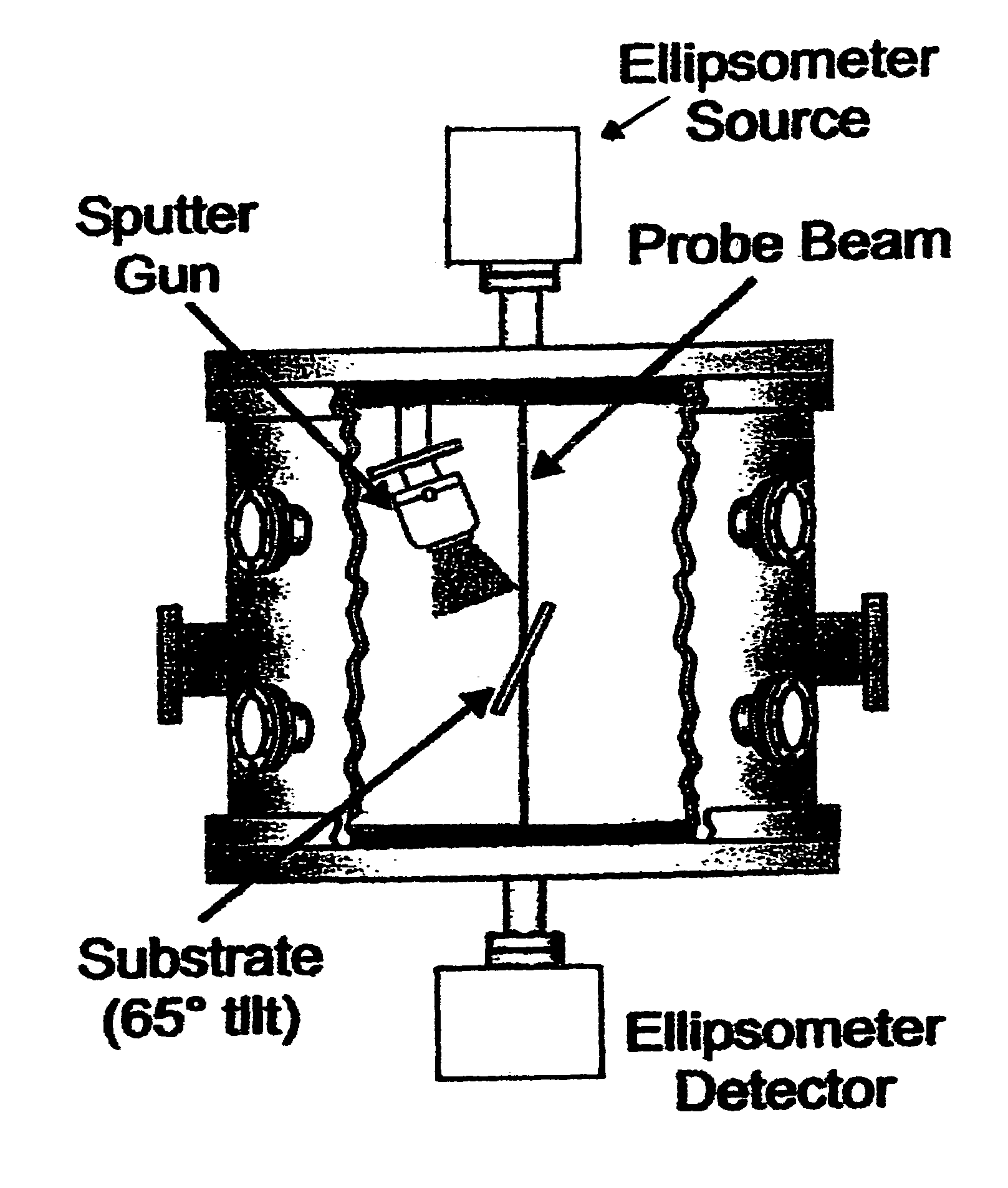
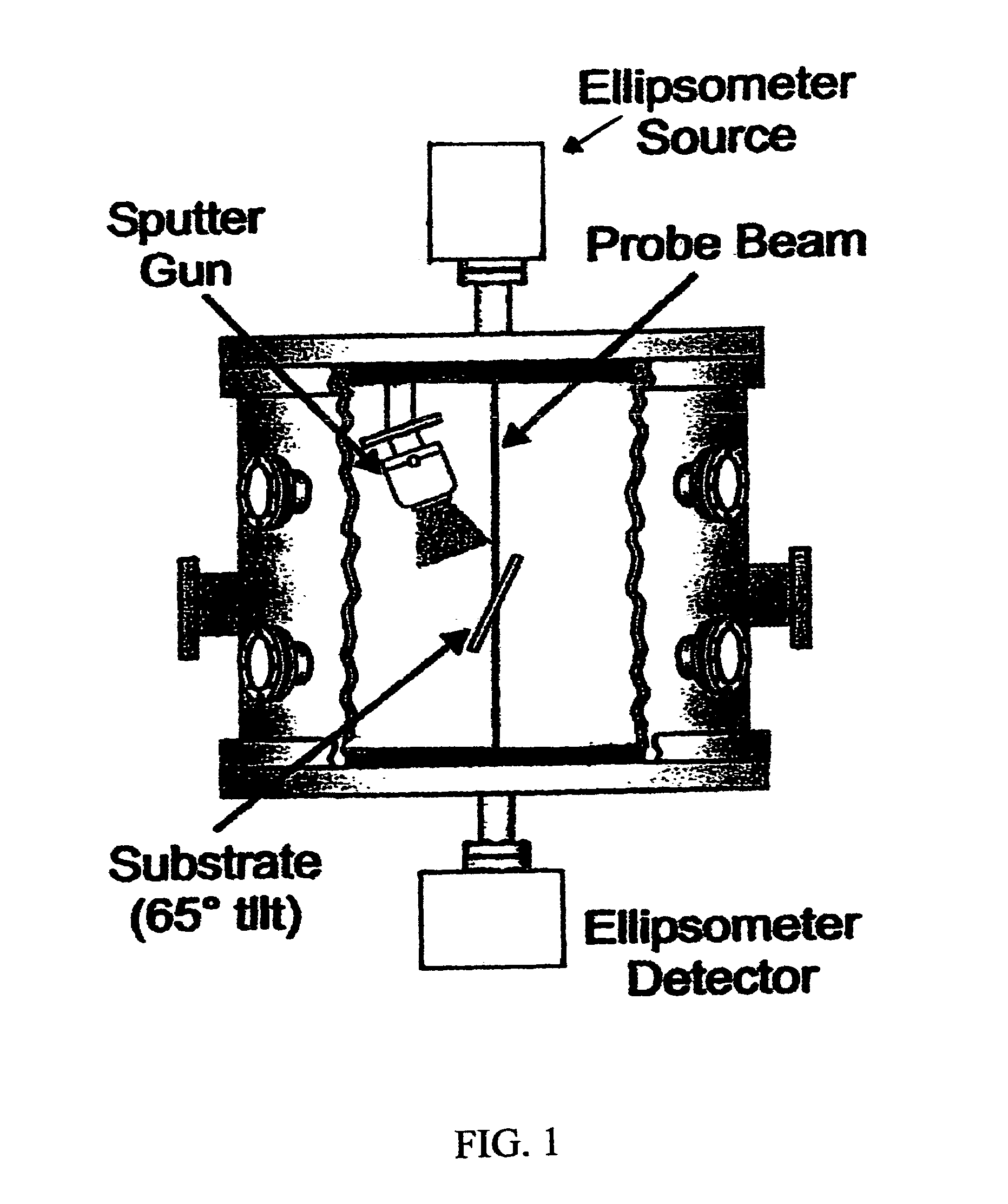
[0051]Turning now to the Drawings, the experimental configuration used to obtain data reported herein is shown in FIG. 1. The deposition system is based on a magnetron sputtering gun where the input gas is injected between the anode and cathode gap. The sputtering gun is tilted approximately 20 degrees from vertical. Gas flow is controlled by an electronic mass flow control system, where argon is used as the sputter gas with a flow rate of 30 sccm. Pure metal sputter targets were used, with a diameter of 54 mm. The target power supply was set to constant DC current mode for all depositions. The system is evacuated by a turbo pump to a base pressure of about 1.3×10⁻⁵ Pa. The pressure during deposition was typically 0.13 Pa. Fused silica substrates (3.2 mm thick) were used to allow in-situ transmission measurements. A substrate optical model, using book value SiO2 optical constants for the substrate with a about 4 SiO surface layer, was developed for the fused silica substrates based ...


PUM


Abstract

Determination of thin metal film dielectric function and layer thicknesses using simultaneous transmission spectroscopic ellipsometric (SE) and transmission intensity (T) measurements obtained in-situ to break correlation between thickness and optical constants of very thin absorbing films, preferably using only A.C. Components of ellipsometric and intensity characterizing electromagnetic radiation which transmits through said substrate and enters a detector.

Description

[0001]This Application Claims Benefit of Provisional Application Ser. No. 60 / 485,007 Filed Jul. 5, 2003.TECHNICAL FIELD[0002]The disclosed invention realtes to determination of thin film dielectric function and layer thicknesses, and more particularly to said determination using simultaneous in-situ transmission spectroscopic ellipsometric (SE) and transmission intensity (T) measurements to break correlation between thickness and optical constants of very thin absorbing metal films.BACKGROUND[0003]Accurate determination of the dielectric function of thin metal films (eg. <10 nm) by ex-situ measurements is difficult, because of the discontinuous nature of thereof, and rapid oxidization upon exposure to air. While in-situ ellipsometric measurements during film deposition can avoid this complication, correlation effects complicate unique determination of film thickness and dielectric function from ellipsometric data alone [1]. While utilization of reflection Spectroscopic Ellipsomet...

Claims


Application Information

Patent Timeline
Patent Type & Authority Patents(United States)
IPC IPC(8): G01J4/00G01B11/06
CPCG01N21/211G01B11/0641
Inventor JOHS, BLAINE D.PRIBIL, GREGORY K.
Owner J A WOOLLAM CO
Why Eureka
Try Eureka