Cooler with blower between two heatsinks
- Summary
- Abstract
- Description
- Claims
- Application Information
AI Technical Summary
Benefits of technology
Problems solved by technology
Method used
Image

Examples
Embodiment Construction
[0026]Preferred embodiments of the present invention will be described in detail below with reference to the accompanying drawings. The numbering of components is consistent throughout, with the same components having the same number.
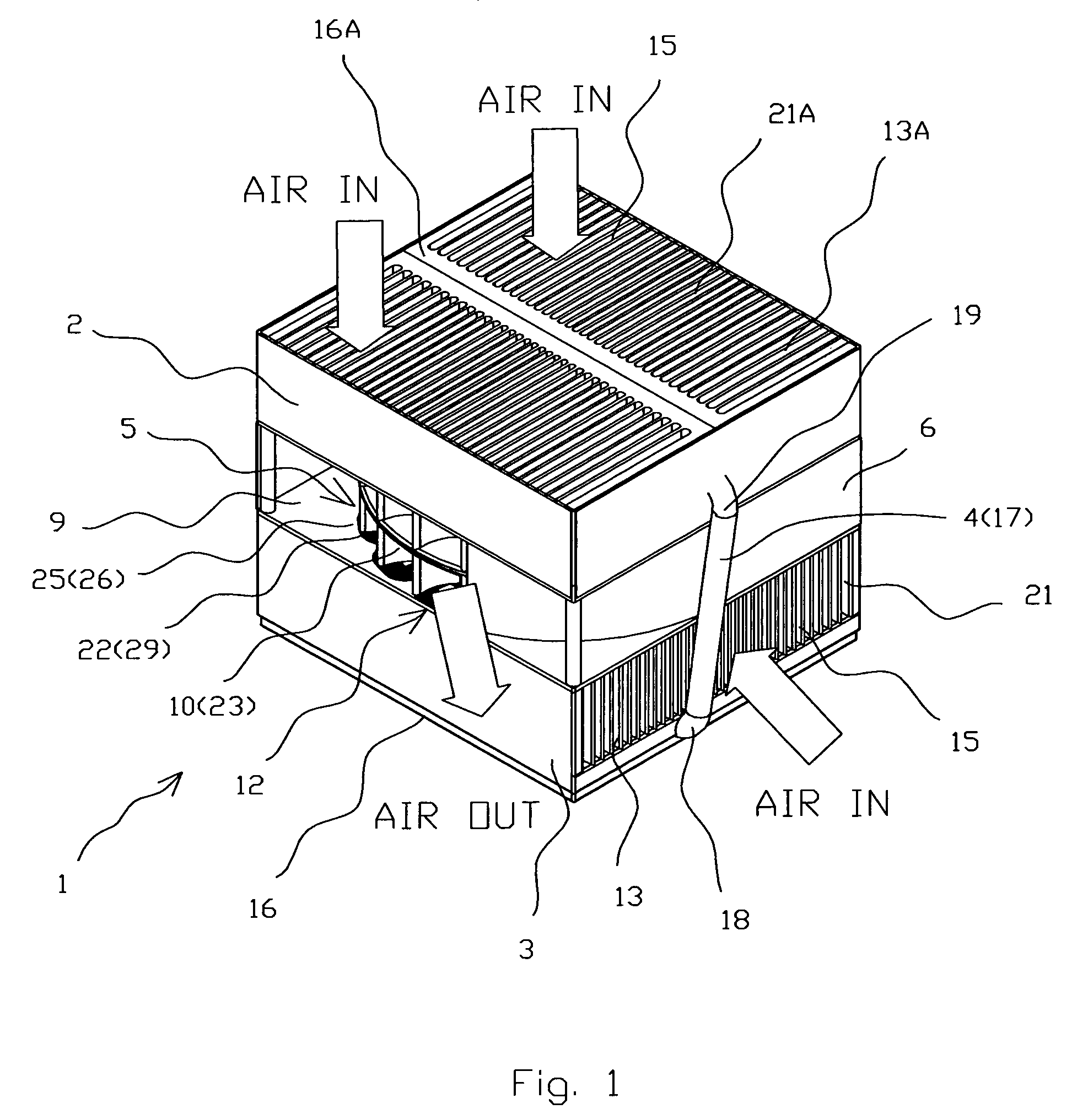
[0027]FIGS. 1–7 show the preferred embodiments of the present invention.
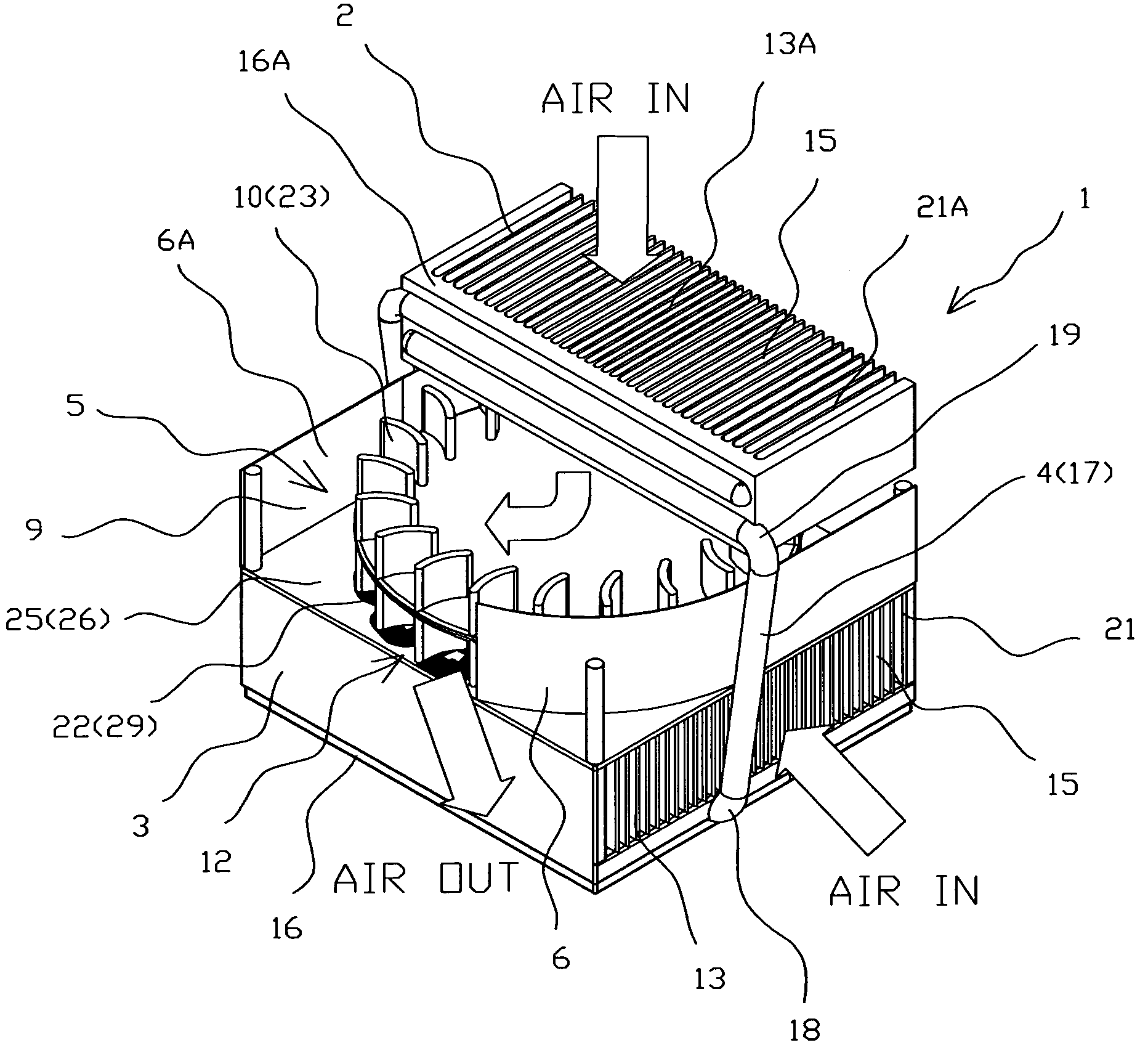
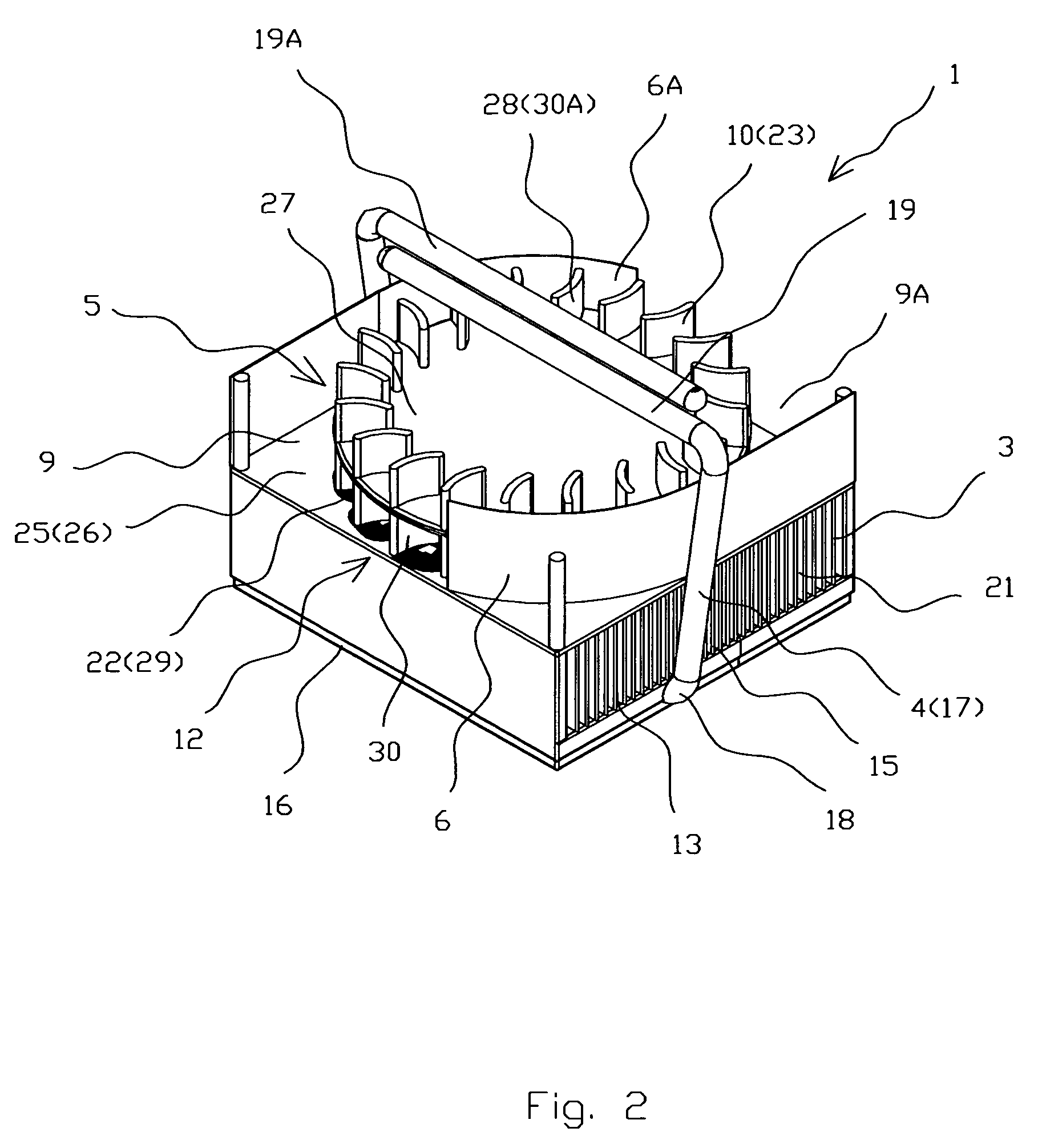
[0028]The cooler 1 for cooling of electronic components (not shown) comprises of at least two heatsinks 2 and 3 thermally connected with each other by heat spreading means 4, and a double inlet centrifugal blower 5 comprising a casing 6 and 6A with two inlets 7 and 8, and an outlet 9, a radial impeller 10 with an axle 11, and an electric drive 12, wherein each of the heatsinks 2 and 3 comprises inflow openings 13 and 13A, outflow openings 14 and 14A, heat exchanging means 15, and bases 16 and 16A providing thermal contact with the heat exchanging means 15. The impeller 10 comprises two sets of radial blades 30 and 30A located from both sides of an impeller disk 27. The double inlet ...
PUM
 Abstract
Description
Claims
Application Information
 - R&D
- Intellectual Property
- Life Sciences
- Materials
- Tech Scout
- Unparalleled Data Quality
- Higher Quality Content
- 60% Fewer Hallucinations
Browse by: Latest US Patents, China's latest patents, Technical Efficacy Thesaurus, Application Domain, Technology Topic, Popular Technical Reports.
© 2025 PatSnap. All rights reserved.Legal|Privacy policy|Modern Slavery Act Transparency Statement|Sitemap|About US| Contact US: help@patsnap.com