Circuit-constituting unit and method of producing the same

a technology of circuit-constituting unit and circuit-forming unit, which is applied in the direction of high-current circuit adaptation, electrical apparatus contruction details, association of printed circuit non-printed electric components, etc., can solve the problems of insufficient compactness of overall construction, inability to make it sufficiently compact in size, and inability to reduce height, etc., to achieve simple structure, reduce overall construction thickness, and simplify construction

Inactive Publication Date: 2007-01-23
AUTONETWORKS TECH LTD +2
View PDF20 Cites 23 Cited by
  • Summary
  • Abstract
  • Description
  • Claims
  • Application Information

AI Technical Summary

Benefits of technology

[0044]Although the flexure-suppressing bus bar may be one specially designed for suppressing the flexing of the insulative base member, preferably, at least one of the specified bus bars extends in a direction generally parallel to the direction of juxtaposing of the specified bus bars, and serves also as the flexure-suppressing bus bar. With this construction, the above effect can be achieved with the simple structure, that is, without increasing the number of the bus bars.
[0045]Although the insulative base member may be merely in the form of an insulative sheet, preferably, the insulativ

Problems solved by technology

Therefore, as a result of the introduction of the FETs, this electric connection box can be made more compact than the conventional electric connection box of the relay type, but the overall construction thereof is complicated, and can not be made sufficiently compact in size, and particularly there has been encountered a problem that the height thereof must be reduced.
And besides, in the above electric connection box, the FETs are provided between the bus bar board and the control circuit board, and therefore heat, generated from the FETs, is liable to remain in the space between the two boards, and therefore it is necessary to adopt a complicated structure for radiating this heat.
Furthermore,

Method used


Image

  • Circuit-constituting unit and method of producing the same
  • Circuit-constituting unit and method of producing the same
  • Circuit-constituting unit and method of producing the same

Examples


Embodiment Construction

The First Preferred Embodiment

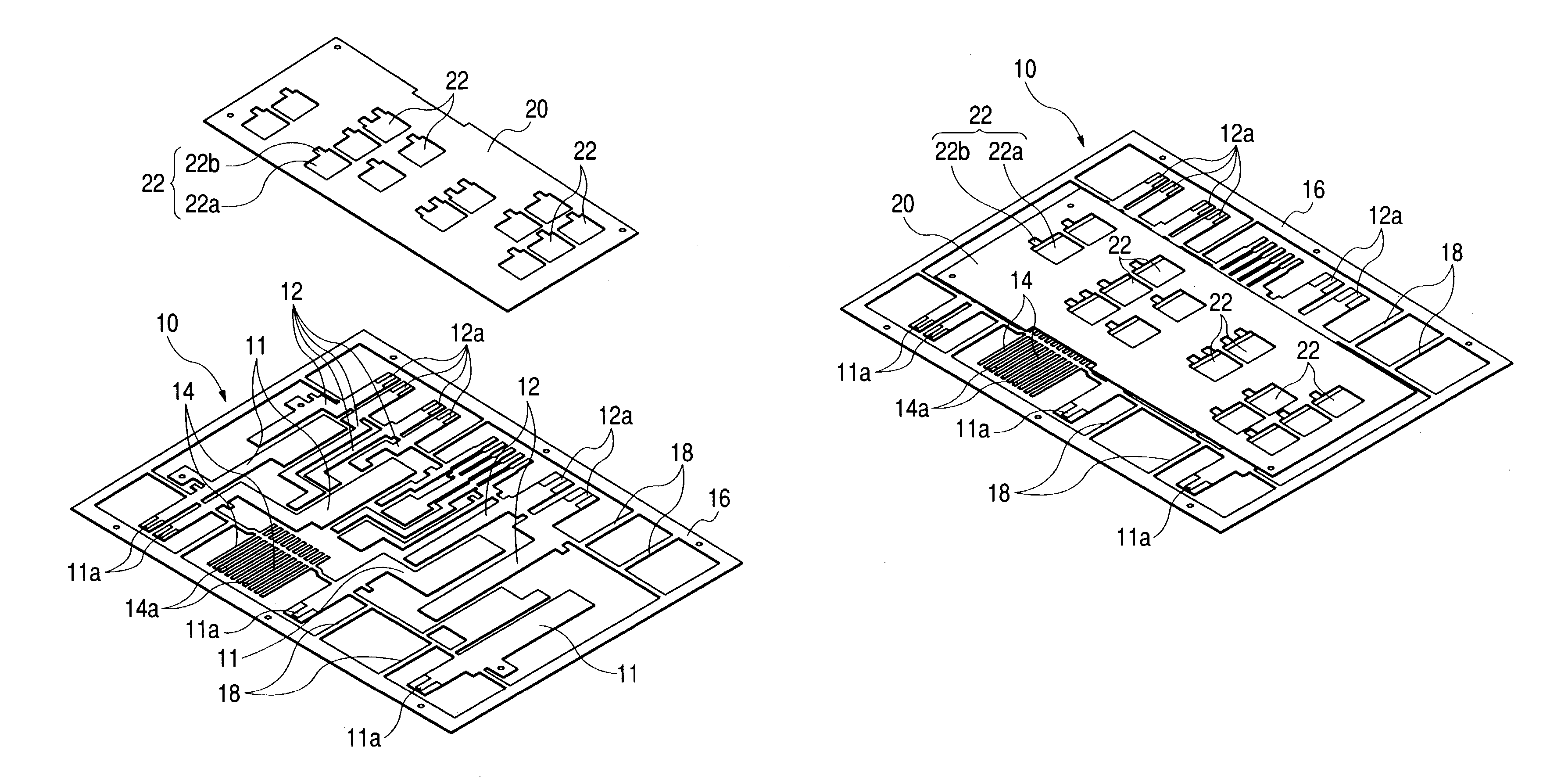
[0069]A first preferred embodiment of the present invention will now be described with reference to the drawings. Here, although there will be described a method of producing a circuit-constituting unit forming a distribution circuit for distributing electric power, supplied from a common power source mounted on a vehicle or the like, to a plurality of electrical loads, the circuit-constituting unit of the invention is not limited to such use, and can be extensively applied to the case where the on / off switching of the energization in a power circuit is effected by semiconductor switching devices.

[0070]1) Bus Bar-Forming Step

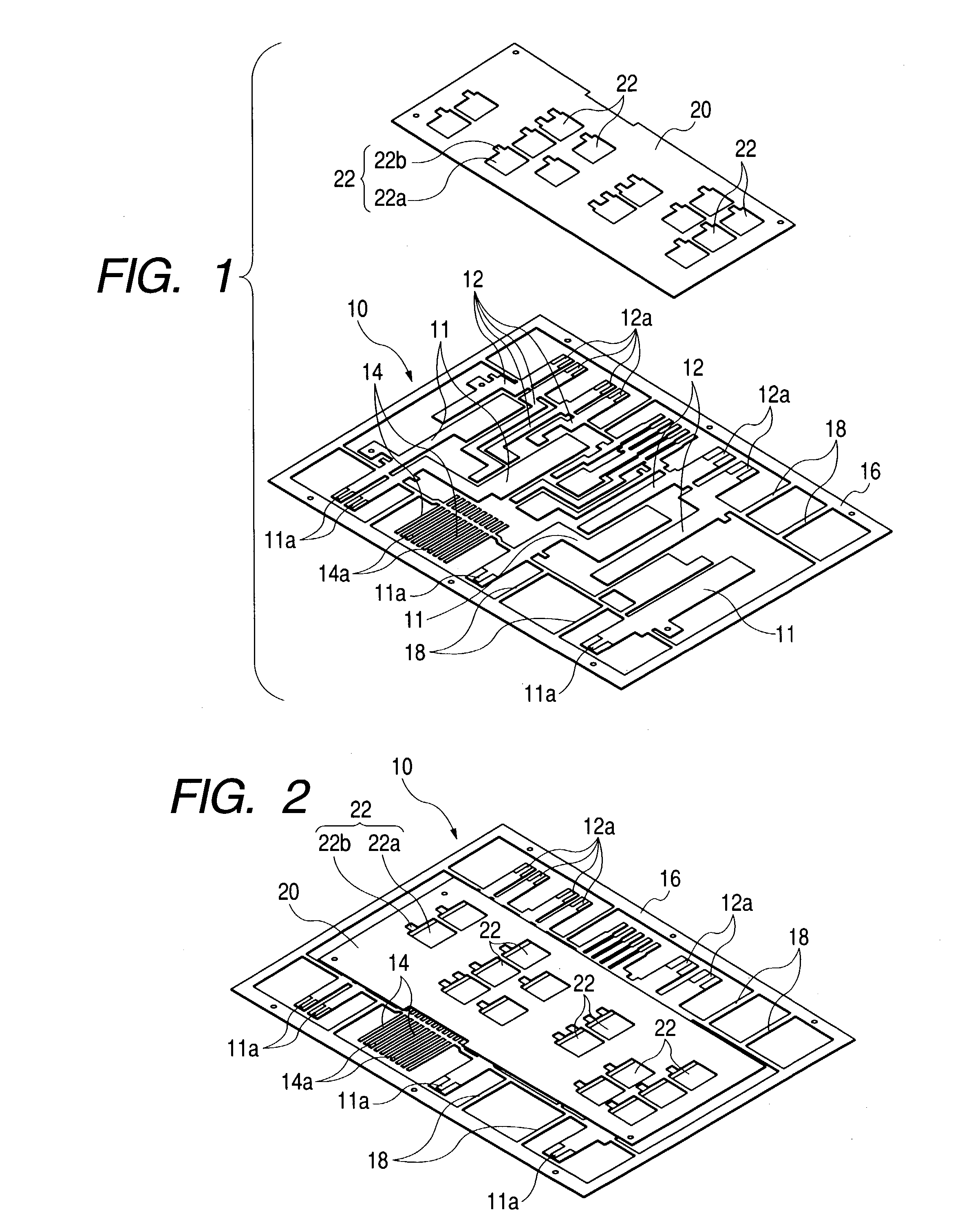
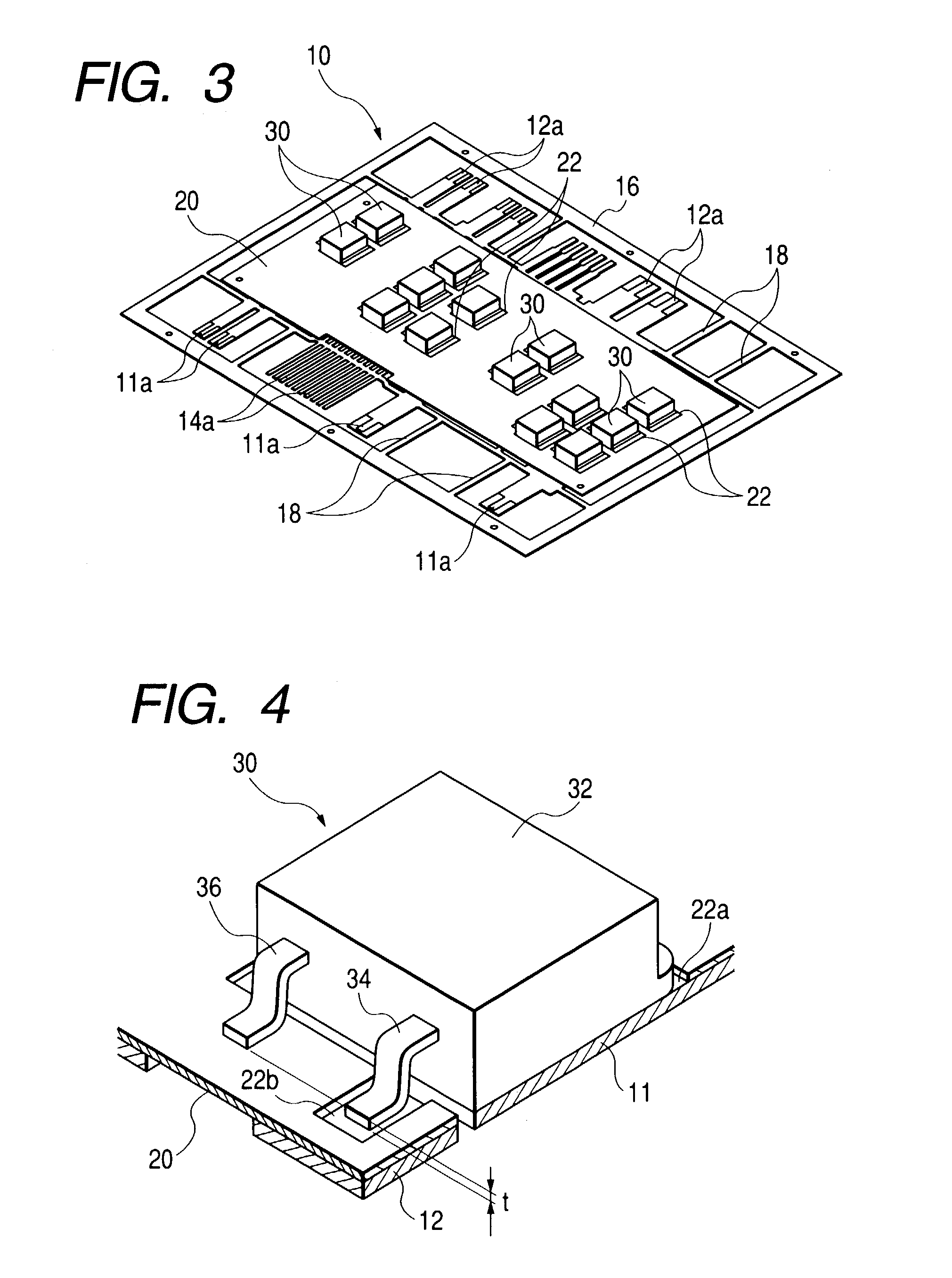
[0071]For producing the above circuit-constituting unit, first, a bus bar-constituting plate 10 as shown in FIG. 1 is formed.

[0072]The illustrated bus bar-constituting plate 10 has an outer frame 16 of a rectangular shape, and within this outer frame 16, a number of bus bars, including a plurality of input terminal bus bars 11, form...


PUM


Abstract

A circuit-constituting unit forming a distribution circuit or the like in a vehicle. The circuit-constituting unit includes a plurality of bus bars for constituting a power circuit; a semiconductor switching device provided in the power circuit; and a control circuit board. The bus bars are bonded to a surface of the control circuit board such that the bus bars are arranged to be generally coplanar with each other. The semiconductor switching device is mounted on both of the corresponding bus bars and the control circuit board. An opening may be formed through the control circuit board. In this case, one of terminals of the semiconductor switching device may be connected to a surface of the control circuit board facing away from the surface to which the bus bars are bonded. The other terminals may be connected respectively to the bus bar through the opening.

Description

BACKGROUND OF THE INVENTION[0001]1. Field of the Invention[0002]This invention relates to a circuit-constituting unit forming a distribution circuit or the like, and to a method producing the same.[0003]2. Background Art[0004]As conventional means for distributing electric power to electrical loads from a common power source, there is known an electric connection box of the type in which a plurality of bus bar boards are stacked together to form a distribution circuit, and fuses and relay switches are incorporated in this circuit.[0005]In recent years, in order to achieve a compact design and high-speed switching control of such an electric connection box, there has been developed the type of circuit-constituting unit in which instead of using the relays, circuit elements, such as FETs, are provided.[0006]For example, JP-A-10-35375 discloses an electric connection box which comprises a bus bar board, forming a current circuit, FETs (semiconductor switching devices), incorporated in ...

Claims


Application Information

Patent Timeline
IPC IPC(8): H01R9/00H05K1/02H05K1/14H05K1/18H05K3/20H05K7/02
CPCH05K1/0263H05K3/202H05K7/026H05K1/0203H05K1/144H05K1/183H05K2201/10969H05K2201/0352H05K2201/0391H05K2201/10166H05K2201/10272
Inventor ONIZUKA, TAKAHIROISSHIKI, ISAONAKANISHI, RYUJITAKAGI, KOUICHICHIN, TOUYAMANE, SHIGEKI
Owner AUTONETWORKS TECH LTD
Why Eureka
Try Eureka