Electrode line

a technology of electrode lines and piezoelectric crystals, applied in the field of electrode lines, can solve the problems of insufficient stability of control mechanisms which are operated with piezoelectric crystals or shape memory alloys, and achieve the effect of facilitating the operation of introducing electrode lines

Inactive Publication Date: 2007-01-23
BIOTRONIK MESS UND THERAPIEGERAETE GMBH & CO
View PDF24 Cites 2 Cited by
  • Summary
  • Abstract
  • Description
  • Claims
  • Application Information

AI Technical Summary

Benefits of technology

[0005]The object of the present invention is attained by the subject of accompanying claim 1. The electrode line of claim 1 is characterized by a structural element in the region of the distal end, which structural element has an electrostrictive polymer and which can be connected by way of at least one electrical line to a voltage source and is adapted to change its shape when an electrical voltage is applied. Electrostrictive polymers have the property of changing their shape, in particular contracting, when a voltage is applied thereto. Therefore it is possible to move the distal end of the electrode line by means of the structural element with the electrostrictive polymer. That represents a control mechanism with which the operation of introducing the electrode line is made easier and which replaces a separate guide wire. The electrode line can therefore be of a smaller diameter than one which has a lumen for a separate guide wire. Electrostrictive polymers also have the property of being flexible. They can withstand a multiplicity of passive flexing movements without becoming brittle or damaging the adjoining electrode or the sheath thereof. Therefore the electrode according to the invention is suitable for permanent implantation.

Problems solved by technology

The control mechanisms which are operated with piezoelectric crystals or shape memory alloys however are usually not sufficiently stable in the long term.

Method used


Image

  • Electrode line
  • Electrode line
  • Electrode line

Examples


Embodiment Construction

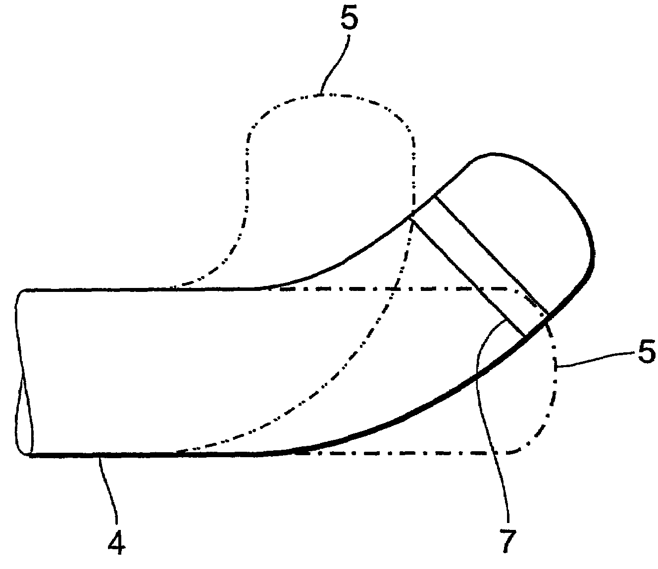
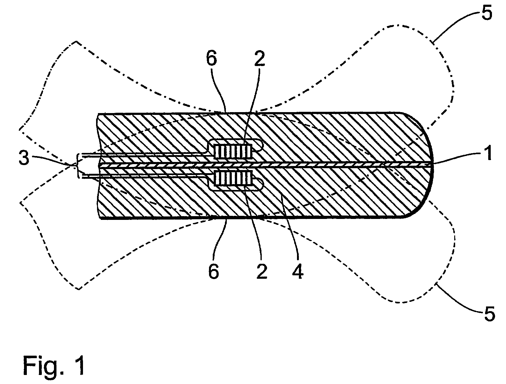
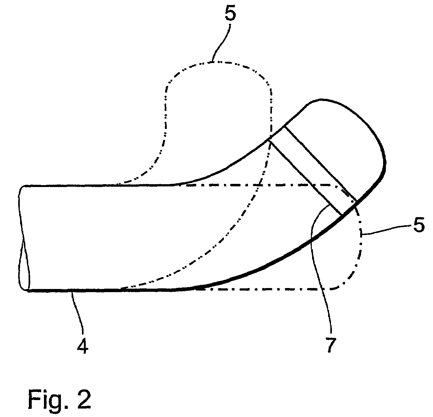
[0018]FIG. 1 shows a side view in section of an electrode line. The electrode 1 extends along the longitudinal axis of the electrode line and is surrounded by a flexible electrode sheath 4. The broken lines show the outline of the electrode line when it has been curved. This will be discussed in greater detail hereinafter. Two structural elements 2 are integrated in the electrode sheath 4 on opposite sides of the electrode 1. The structural elements 2 are each connected to respective ones of two electrical feed lines 3 which lead to the proximal end (not shown) of the electrode line and are there connected to a voltage source. The two structural elements 2 can be actuated separately. The structural elements 2 each have a respective electrostrictive polymer which changes its shape when a voltage is applied. In the preferred embodiment the application of a voltage to one of the two structural elements 2 causes them to be contracted in the direction of the longitudinal axis. By virtue ...


PUM


Abstract

An electrode line, in particular for an implantable electrostimulation device, which is adapted for insertion into body vessels such as heart chambers or blood vessels, comprising electrodes for the stimulation of body tissue, a longitudinal axis and a distal end, wherein there is provided at least one structural element (2) in the region of the distal end, which has an electrostrictive polymer and which can be connected to a voltage source by way of at least one electrical feed line (3) and which is adapted to change its shape when an electrical voltage is applied.

Description

[0001]The invention concerns an electrode line, in particular for an implantable electrostimulation device, which is adapted for insertion into body tissue such as heart chambers or blood vessels, and has electrodes for the stimulation of body tissue, a longitudinal axis and a distal end.BACKGROUND OF THE INVENTION[0002]Electrode lines are preferably used to electrically stimulate surrounding body tissue or record electrical signals. They are used in particular also in the region of the coronary vessels or veins in order to control heart contraction. For that purpose, the requirement is that the electrode can be introduced into the selected vessel. That should be implemented with minimum invasion in order to save the patient major stress levels. If the electrode is to be disposed in the coronary sinus at the left atrium or in one of the adjoining veins at the left ventricle, then access takes place in the following fashion: the electrode is firstly passed through a transvenous or ve...

Claims


Application Information

Patent Timeline
Patent Type & Authority Patents(United States)
IPC IPC(8): A61N1/00A61N1/05
CPCA61N1/056A61N2001/0585
Inventor REINKE, HEINRICHSCHALDACH, JR., LEGAL REPRESENTATIVE, MAXSCHALDACH, DECEASED, MAX
Owner BIOTRONIK MESS UND THERAPIEGERAETE GMBH & CO
Why Eureka
Try Eureka