Method and apparatus of driving torsional resonance mode of a probe-based instrument

a technology of torsional resonance and probe-based instruments, which is applied in the direction of instruments, mechanical roughness/irregularity measurements, measurement devices, etc., can solve the problems of loss of inability to provide shear force or force gradient information, and inability to provide other information relating to the sample, etc., to achieve optimal data acquisition capabilities

Inactive Publication Date: 2007-01-30
BRUKER NANO INC
View PDF19 Cites 15 Cited by
  • Summary
  • Abstract
  • Description
  • Claims
  • Application Information

AI Technical Summary

Benefits of technology

[0030]The preferred embodiments overcome the above-noted drawbacks by aligning the rotational center produced by the torsional resonance mode drive with the tip so that pure torsional motion can be obtained. In the preferred embodiment, the power provided by the two piezos driving the cantilever into torsional resonance is generated by applying signals out of phase with each other and having varying amplitudes so as to distribute power such that the rotational center of the motion directly overlies the apex of the tip. More particularly, by appropriately modifying the amplitudes of the signals applied to the piezo plates, the rotational center of the cantilever can be moved to produce ideal torsional motion and optimum data acquisition capabilities in torsional resonance (TR) mode.
[0031]According to a first aspect of the preferred embodiment, a method of operating a scanning probe microscope includes using a probe having a cantilever and oscillating the probe at a torsional resonance frequency thereof. In addition, the method includes substantially maximizing an amplitude of probe oscillation.

Problems solved by technology

One limiting characteristic of AFMs and other probe-based instruments lies in the above-described modes of operation.
As a result, flexural mode AFMs do not detect shear force interaction, and thus also cannot provide shear force or force gradient information.
Moreover, without shear force or shear force gradient measurement capabilities, flexural mode operation often results in loss of other information relating to the sample.
This limitation also holds true for electric force imaging.
Other drawbacks associated with flexural resonance imaging are slow kinetics and small amplitude errors that can drastically limit scanning and data acquisition speed and compromise image integrity.
The speed of data acquisition must be correspondingly limited as well.
As a result, the control error will correspond to a greater quantity of height measurement error.
The situation is particularly problematic when the probe is scanning across an abrupt step where slower response due to error integration will result in even greater inaccuracy for a given scan speed.
Notably, such inaccuracy may be detrimental to obtaining useful data in semiconductor metrology.
Yet another limitation with flexural mode operation is that the flexural resonance is very sensitive to the imaging environment (e.g., when the sample is immersed in water), and thus oscillation properties often change drastically, and in unpredictable ways, upon change in imaging environment.
Other modes of AFM operation are similarly limited.
In addition to the drawbacks associated with using contact mode to detect topology characteristics, including tip / sample damage, etc., LFM suffers the disadvantage of large tip / sample forces associated with contact mode, and poor repeatability.
However, the lateral deflection signals are small, and thus often unusable, and resolution is insufficient for some of the applications contemplated by the present invention.
In addition, although lateral deflection signals induced by motion of the sample at acoustic frequencies can be enhanced, the main control loop that defines tip / surface relative position still employs vertical deflection (contact mode) feedback and, therefore, suffers the drawbacks associated with flexural contact modes.
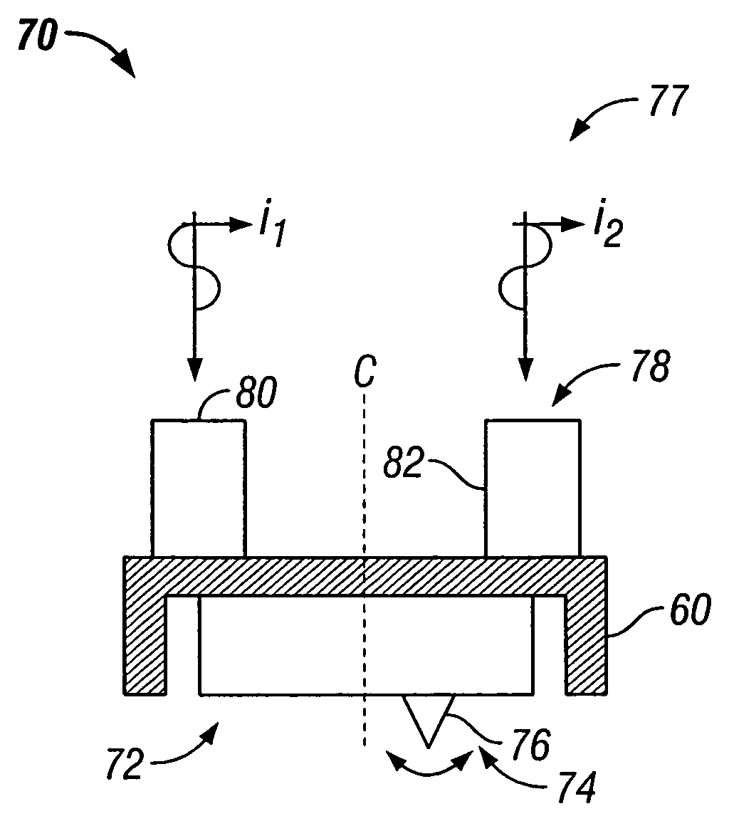
One challenge in implementing an AFM to image in torsional resonance mode is that optimum performance depends on efficiently driving the cantilever probe into torsional resonance.
A potential problem arises with standard AFM cantilevers designed for flexural oscillation due to the fact that there is physical asymmetry along the corresponding length of the lever which although acceptable when driving the probe into flexural oscillation, can render driving the cantilever into pure torsional resonance difficult.
The problem is, it is difficult to insure that the central axis of the probe lies at the rotation center of the drive.
For instance, mounting the probe (i.e., probe chip) in the AFM head is often an imprecise task due to allowable variations in probe chip position, as well as structural variations of the probe chip and probe itself.
In addition, even if the actuators are positioned equidistant from the central axis of the cantilever, due to fabrication limitations, it is difficult to determine whether the drive actuators are positioned symmetrically about the tip which, although preferably resides at the central axis of the lever, often does not.
Notably, in this regard, the tip of the probe attached to the lever is relatively massive (it can be as much as fifteen microns long) such that the inertia of the tip causes a torque.
Overall, however, it is difficult to determine the amount of lateral motion that can be provided by such a system due to inefficiencies coupling the energy to the tip caused by the imperfect spatial relationship between the probe tip and the drive.
As a practical matter, however, because the tip typically is not centered, due to, for example, imperfections produced during the probe manufacturing process which may cause the tip to be positioned off the central axis of the cantilever or the entire probe to be mounted off-center intermediate the two piezo plates when secured in the AFM head.
Whatever the cause, this compromised relationship between the drive and the probe can produce imperfect lateral motion of the cantilever, and thus the tip.
Such non-ideal motion lowers the efficiency of operation in torsional resonance mode.
For instance, a vertical component in the cantilever motion can make maintaining operation at the setpoint difficult.
Therefore, the vertical component of cantilever motion may become mixed with torsional oscillation such that the system becomes very unstable, with the possibility that AFM operation toggles between, for instance, torsional resonance and flexural resonance modes of AFM operation.
Clearly, this unpredictability is non-ideal.
Given the scale of operation, one key challenge in using an AFM probe to perform nanomanipulation is determining whether a particular operation associated with manipulating nanoparticles has actually been accomplished.
In standard AFM operation, once a target to be manipulated has been identified and an operation attempted by the AFM probe, there is no convenient way to determine whether the target has actually been acted on.
However, because the target to be manipulated typically does not have an appreciably greater weight than the tip, methods based on directly measuring a change in weight are unreliable and, in any event, difficult to implement.
In fact, there is such a small change in mass at the tip, e.g., one part in a million of the entire cantilever, directly measuring the change is generally impossible.
In addition, known techniques for performing nanomanipulation, such as ones that employ what are known as “nanotweezers,” have significant limitations.
Most such techniques only have the ability to manipulate targets that are on the scale of a micron or even a little larger.
This is due to the fact that there are often difficulties associated with locating the tweezers at a location of interest, and controlling the force applied by the tweezers to the sample, for example.
One problem with such a system is that large magnitude forces are required to close the arms, which can compromise the object being manipulated.
Moreover, in this regard, the dimensions of candidate target objects to be manipulated are correspondingly limited in that objects that are too small cannot be feasibly manipulated, especially given the higher voltages, and thus the higher forces, that are difficult to accurately control.

Method used


Image

  • Method and apparatus of driving torsional resonance mode of a probe-based instrument
  • Method and apparatus of driving torsional resonance mode of a probe-based instrument
  • Method and apparatus of driving torsional resonance mode of a probe-based instrument

Examples


Embodiment Construction

[0064]A probe-based instrument, such as an AFM, that analyzes one or more characteristics of a sample in a torsional resonance mode is shown in the Figures and described herein. More particularly, a number of techniques for generating a steady torsional resonance in the cantilever of the SPM probe assembly is discussed. TR mode, together with feedback control, is used to image or otherwise characterize sample surfaces.

[0065]During operation, a property of a torsional oscillation of the probe (e.g., amplitude or phase of probe oscillation about the longitudinal centerline of the probe's cantilever) is monitored to determine sample surface characteristics. Notably, the torsional signal detection and feedback control is preferably implemented using configurations similar to that used in known AFMs, such as in the AFMs offered by the Veeco Instruments Inc. However, compared to known AFM operating modes, including flexural oscillation mode operation, the potential benefits of the present...


PUM


Abstract

A method of operating a scanning probe microscope includes using a probe having a cantilever, and oscillating the probe at a torsional resonance frequency thereof. In addition, the method includes substantially increasing torsional drive efficiency with dual actuators disposed on the probe or the probe base. First and second actuators may be driven by corresponding first and second drive signals, the first and second drive signals being about 180° out of phase. The maximizing step includes altering at least one of the amplitudes of the first and second drive signals to maximize torsional oscillation. Torsional and flexural oscillation of the cantilever probe can be excited concurrently, sequentially or independently by adjusting the phase of the corresponding drive signals. A pair of cantilever components can be used to form a nanotweezer by rotating the respective arms having corresponding tip portions at the distal ends.

Description

CROSS REFERENCE TO RELATED APPLICATION[0001]This application is a continuation-in-part of U.S. patent application Ser. No. 10 / 189,108 filed on Jul. 2, 2002, now U.S. Pat. No. 6,945,099 the entirety of which is expressly incorporated by reference herein.BACKGROUND OF THE INVENTION[0002]1. Field of the Invention[0003]The present invention is directed operating a probe-based instrument in torsional oscillation mode, and more particularly, a method and apparatus of driving the probe into torsional resonance.[0004]2. Description of Related Art[0005]Several probe-based instruments monitor the interaction between a cantilever-based probe and a sample to obtain information concerning one or more characteristics of the sample. Scanning probe microscopes (SPMs), such as the atomic force microscope (AFM), are devices which typically use a sharp tip and low forces to characterize the surface of a sample down to atomic dimensions. More particularly, SPMs typically characterize the surfaces of su...

Claims


Application Information

Patent Timeline
Patent Type & Authority Patents(United States)
IPC IPC(8): G01B5/28G01Q10/00G01Q10/06G01Q60/24G01Q60/26G01Q60/32G01Q60/34G01Q60/38
CPCB82Y35/00G01Q10/06G01Q60/38G01Q60/32G01Q60/34G01Q60/26
Inventor SU, CHANMINDANIELS, ROBERT C.
Owner BRUKER NANO INC
Why Eureka
Try Eureka