
High-speed cutting process for generating desired curved surface on workpiece

a cutting process and workpiece technology, applied in the direction of optical surface grinding machines, lens, manufacturing tools, etc., can solve the problems of slow lapping process, inability to achieve the desired curvature of the surface of the lens, and inability to achieve the cutting hours needed for machining operation, etc., to achieve the effect of reducing the mass of the slider, and reducing the amount of the slider

Inactive Publication Date: 2007-01-30
WEST ELECTRIC CO LTD
View PDF8 Cites 16 Cited by
  • Summary
  • Abstract
  • Description
  • Claims
  • Application Information

AI Technical Summary

Benefits of technology

This approach significantly reduces processing time by up to 50% and enhances efficiency, enabling the generation of complex surfaces like toric and multifocal lenses with improved precision and reduced cycle time.

Problems solved by technology

The lapping of the workpiece is a slow process because the slow rotating velocity of the workpiece.
This means that the prior lapping machines are ready for finish processing, but seldom possible to generate the desired curvature of the surfaces on the lens.
In the generation of any curved surface on the workpiece, most grinding or lapping operations always cost plenty of time for making any desired surface on the workpiece and, therefore, it remains a major challenge to produce any specific surface on the workpiece with short time.
With the prior machining operation using the NC processor, nevertheless, largely cutting hours needed for machining operation could not be achieved as the work spindle was kept against reciprocating movement in the Z-axis direction during cutting operation on the workpiece.
This has been a major factor in substantial cycle time being needed for forming the desired surface on the workpiece.
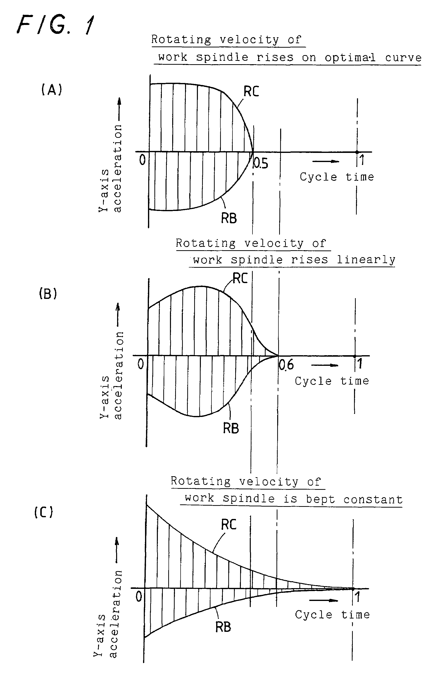
With the prior generating process for the curved surface in which the Y-axis acceleration of the slider gets less as the cutting operation proceeds away from the fringe toward the center of the workpiece, accordingly, it could be said that the slider could not serve the high performance in the Y-axis movement of the slider to the full.
Thus, the process for generating the curved surface on the workpiece still poses the major challenge about how to make the most of the Y-axis acceleration performance of the slider to shorten the time cycle it takes for the curve generation on the workpiece.

Method used


Image

  • High-speed cutting process for generating desired curved surface on workpiece
  • High-speed cutting process for generating desired curved surface on workpiece
  • High-speed cutting process for generating desired curved surface on workpiece

Examples

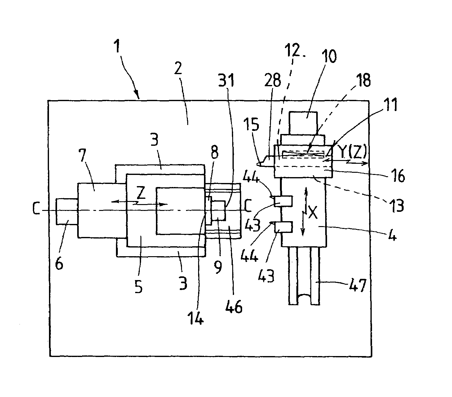
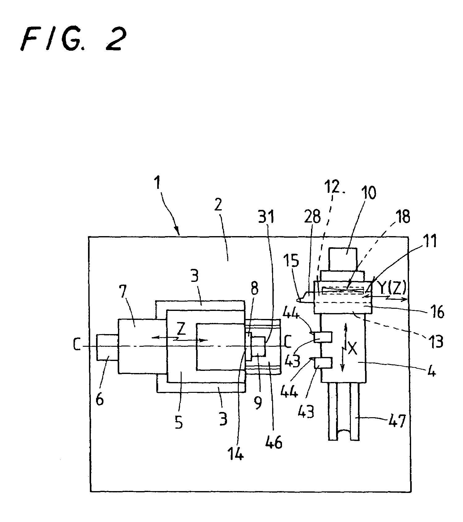

Embodiment Construction

[0034]A preferred embodiment of a process for generating any curved surface on a workpiece with high-speed according to the present invention will be explained hereinafter in detail with reference to the accompanying drawings. Referring first to FIGS. 2 to 5, there is an NC curve generator to carry out the high-speed curve-generating process according to the present invention.

[0035]A high-speed curve generator 1 to carry out the high-speed curve-generating process according to the present invention is comprised of a Z-axis table allowed to move in and out lengthwise of a work spindle 14 on a Z-axis base 46 mounted on a machine bed 2, and an X-axis table 4 allowed to make reciprocation move in an X-axis direction perpendicular to the Z-axis direction on an X-axis base 47 mounted on the machine bed 2. A headstock 5 is supported on the Z-axis table 3, which is forced to move in and out in the Z-axis direction by actuation of a servomotor 6 attached to the Z-axis base 46. The headstock ...


PUM

PropertyMeasurementUnit
speedaaaaaaaaaa
radiusaaaaaaaaaa
curvatureaaaaaaaaaa

Abstract

A process for generating a curved surface on a workpiece with high speed is disclosed, in which an acceleration of a slider is set to a predetermined desired acceleration while a rotating velocity of a work spindle is made varied to keep the acceleration of the slider as constant as possible. Rotation of the work spindle and movement of an X-axis table are made synchronized with the movement of the slider having the desired acceleration to generate a preselected desired curve on a surface of the workpiece, which lies in perpendicular to a Y-axis along which a cutting tool moves in and out, thereby shortening the cycle time it takes for the curve generation on the workpiece.

Description

FIELD OF THE INVENTION[0001]The present invention relates to a process for generating any desired surfaces on an object or workpiece with using a numerical control processor, called herein NC processor. More particularly it relates to a process for generating any preselected specific surfaces including toric surfaces, and so on with high speed or high efficiency on any workpiece such as a plastic lens or the like, hereinafter at times referred to as “high-speed curve-generating process”.BACKGROUND OF THE INVENTION[0002]A variety of optical lenses has been conventionally assembled and used in different types of optical devices, information processors, and so on. The most familiar of the lenses has the symmetrical aspheric or nonspherical surface, which is made by polishing or lapping the surfaces of the cut or molded glass blank with the use of lapping of honing machines to the final form. Many types of the specific lapping machine have been heretofore developed to generate the symme...

Claims


Application Information

Patent Timeline
Patent Type & Authority Patents(United States)
IPC IPC(8): B23B3/00B23Q15/00B23B5/36B23Q5/027B23Q5/28B24B13/00B24B13/06B24B51/00
CPCB23Q5/027B24B13/0012B24B13/06B24B51/00Y10T82/2533Y10T82/10Y10T82/14Y10T82/2502Y10T82/13
Inventor HIRAYAMA, SHINOBUMORIKAWA, TOSHIROMINOHARA, MASAHIROSHINGAI, KOUKI
Owner WEST ELECTRIC CO LTD
Learn More