Self-expanding stent

a self-expanding, stent technology, applied in the field of flexible stents, can solve the problems of stent collapse, stent inside diameter may become smaller, and stent design that has been used with self-expanding stents has certain functional problems

Inactive Publication Date: 2007-01-30
ORBUSNEICH MEDICAL PTE LTD
View PDF95 Cites 126 Cited by
  • Summary
  • Abstract
  • Description
  • Claims
  • Application Information

AI Technical Summary

Problems solved by technology

One problem with balloon stents is that the inside diameter of the stent may become smaller over time if the stent lacks expanding resilience.
The result of this lack of resilience is that the stent collapses due to the natural elastic recoil of the blood vessel.
Each of the various stent designs that have been used with self-expanding stents has certain functional problems.
Consequently, insertion of the stent into the affected region of a vessel may be very difficult.
A stent formed from a zigzag pattern has flexibility in the axial direction to facilitate delivery of the stent, however, this type of stent often lacks sufficient radial strength to maintain patentcy of the vessel after elastic recoil.
Connection elements between each adjacent undulating portion may impair flexibility of the stent.
Consequently, these types of stents have a comparatively high degree of rigidity and do not bend to accommodate changes in vessel shape.

Method used


Image

  • Self-expanding stent
  • Self-expanding stent
  • Self-expanding stent

Examples


Embodiment Construction

[0027]The present invention relates to a self-expanding stent. A stent means any medical device which when inserted into the lumen of a vessel expands the cross-sectional lumen of that vessel. The stent of the invention may be deployed in any artery, vein, duct or other vessel such as a ureter or urethra. The stents may be used to treat narrowing or stenosis of any artery, including, the coronary, infrainguinal, aortoiliac, subclavian, mesenteric or renal arteries.

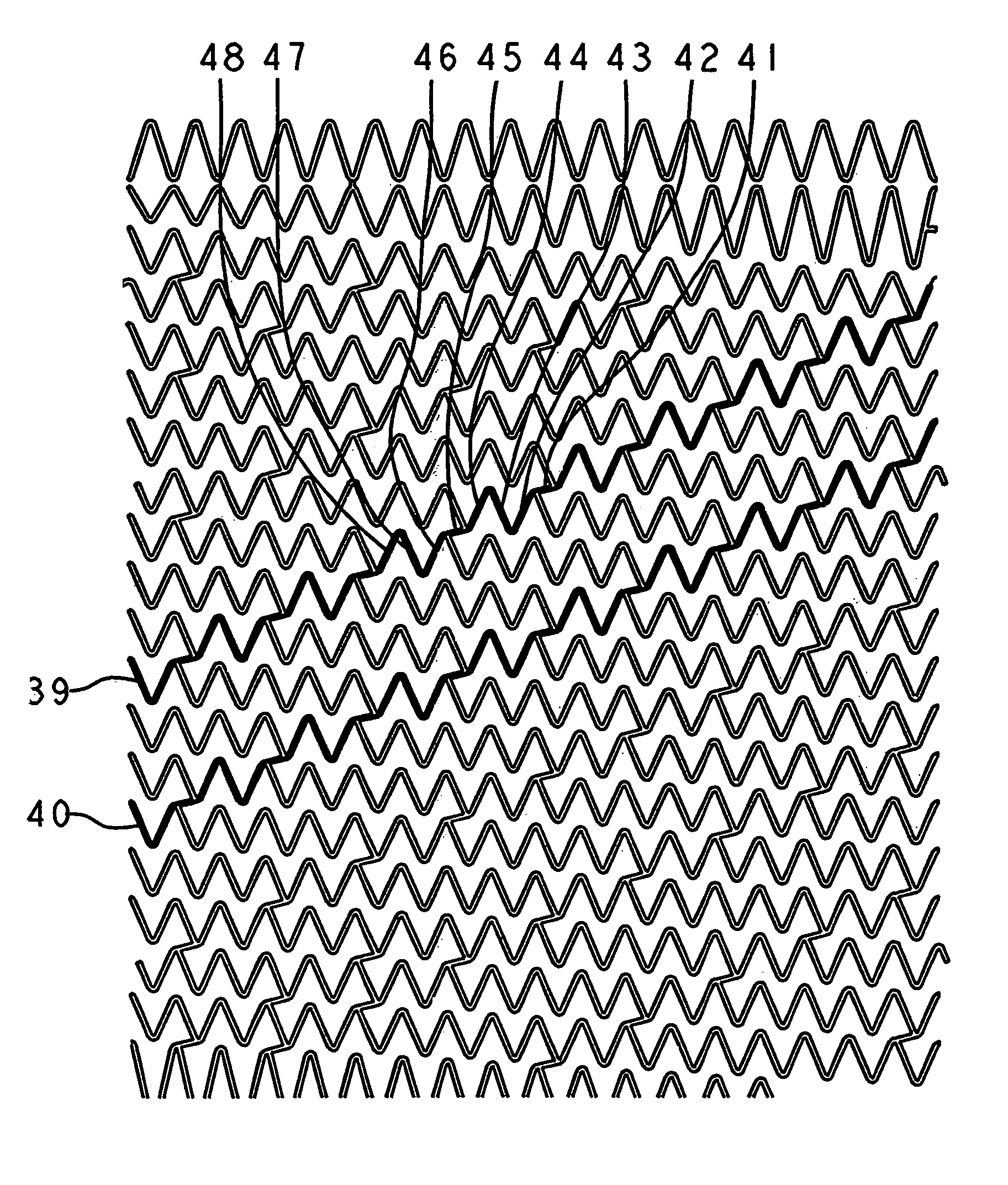
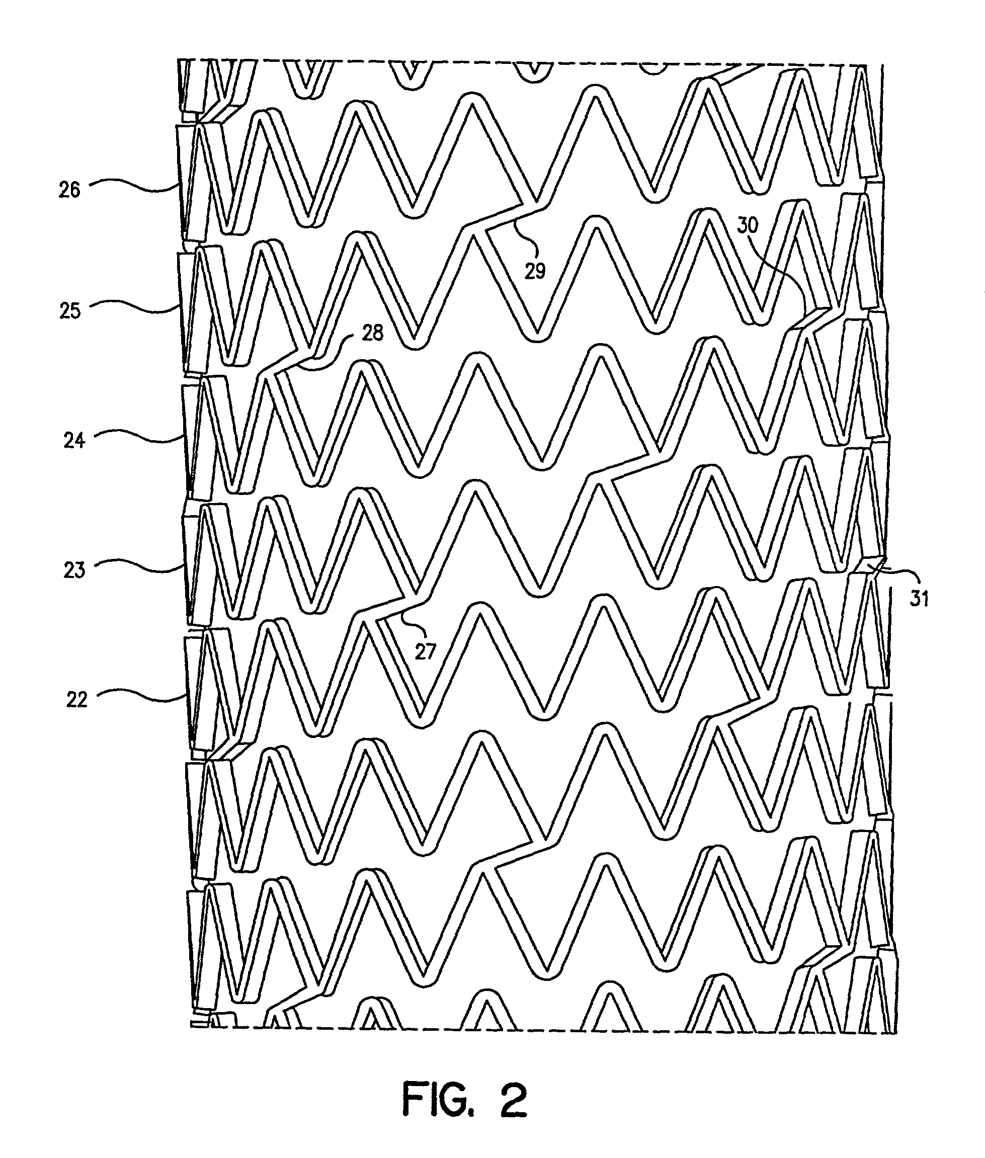
[0028]The term “undulation” refers to the bends in elements forming the first type of helix in the stent. Undulations may be formed in a sinusoidal, zigzag pattern or similar geometric pattern.

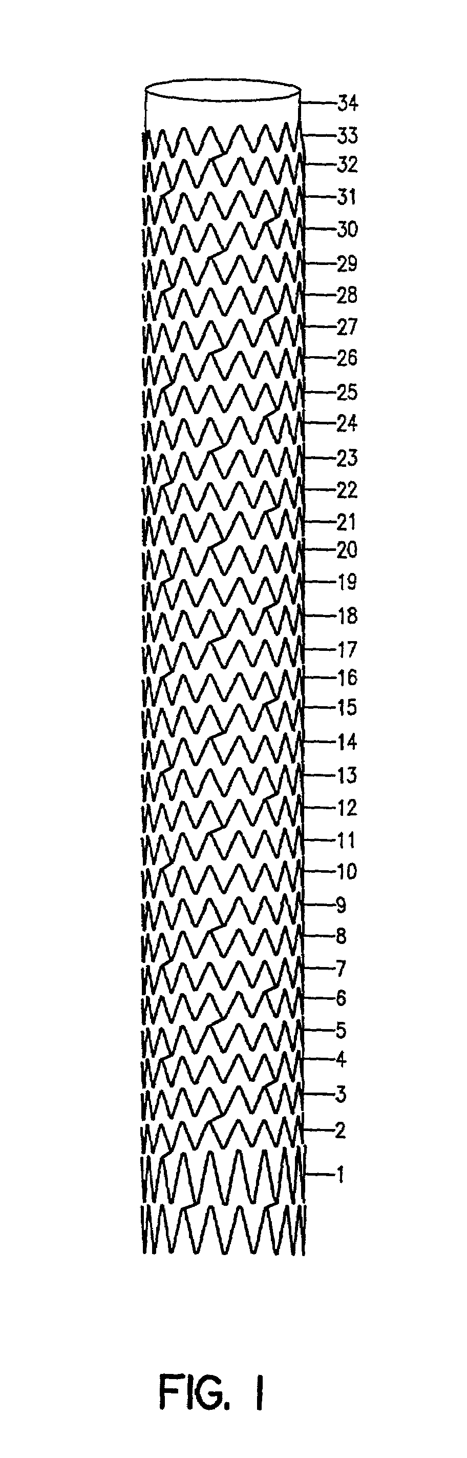
[0029]The stent comprises a hollow cylindrical member having no free ends and a wall surface. The wall may have a substantially uniform thickness. In the compressed state, the stent has a first diameter. This compressed state may be achieved using a mechanical compressive force. The compressed state permits intraluminal delivery of t...


PUM


Abstract

The stent of this invention is a self-expanding stent created by a scaffolding lattice. The stent may be made from a nickel-titanium alloy. The lattice is formed from two different types of helices that proceed circumferentially in opposite directions along the longitudinal axis of the stent. The helices have no free ends. The first type of helix is formed by a series of undulations and the second type of helix is formed from a series of connection elements. The undulations may be in a zigzag or sinusoidal pattern. The connection elements connect the junction points lying on adjacent turns of the first type of helix. The junction points are formed by the ascending and descending arms of the undulations or zigzags. The ends of the stent may be formed by a closed circumferential element which is linked by connection elements to a transition zone. The transition zone is formed by a closed loop that connects directly to the first helix. The amplitude of the undulations or zigzags forming the transition zone increases from the closed loop to the point connecting the transition zone with the first type of helix. The closed circumferential element may be made from a radiopaque material. The scaffolding lattice design of the stent provides a stent having a high degree of flexibility as well as radial strength.

Description

[0001]This application claims the benefit of U.S. Provisional Application No. 60 / 206,211, filed May 22, 2000.FIELD OF THE INVENTION[0002]The present invention relates to flexible stents that are implanted in a lumen in the body and in particular in blood vessels.BACKGROUND OF THE INVENTION[0003]Stents are scaffolds which are positioned in diseased vessel segments to support the vessel walls. Stents are used in angioplasty to repair and reconstruct blood vessels. Placement of a stent in the affected arterial segment prevents elastic recoil and closing of the artery. Stents also prevent local dissection of the artery along the medial layer of the artery. Stents may be used inside the lumen of any physiological space, such as an artery, vein, bile duct, urinary tract, alimentary tract, tracheobronchial tree, cerebral aqueduct or genitourinary system. Stents may also be placed inside the lumen of human as well as non-human animals.[0004]In general there are two types of stents: radially...

Claims


Application Information

Patent Timeline
Patent Type & Authority Patents(United States)
IPC IPC(8): A61F2/86A61F2/84A61F2/88A61F2/90
CPCA61F2/88A61F2/915A61F2002/91508A61F2230/0054A61F2002/91533A61F2002/91558A61F2002/91525A61F2002/91575
Inventor COTTONE, JR., ROBERT JOHNBECKER, GARY JAY
Owner ORBUSNEICH MEDICAL PTE LTD
Why Eureka
Try Eureka