
Image processing system, projector, program, information storage medium, and image processing method

Active Publication Date: 2007-01-30
SEIKO EPSON CORP
View PDF19 Cites 25 Cited by
  • Summary
  • Abstract
  • Description
  • Claims
  • Application Information

AI Technical Summary

Benefits of technology

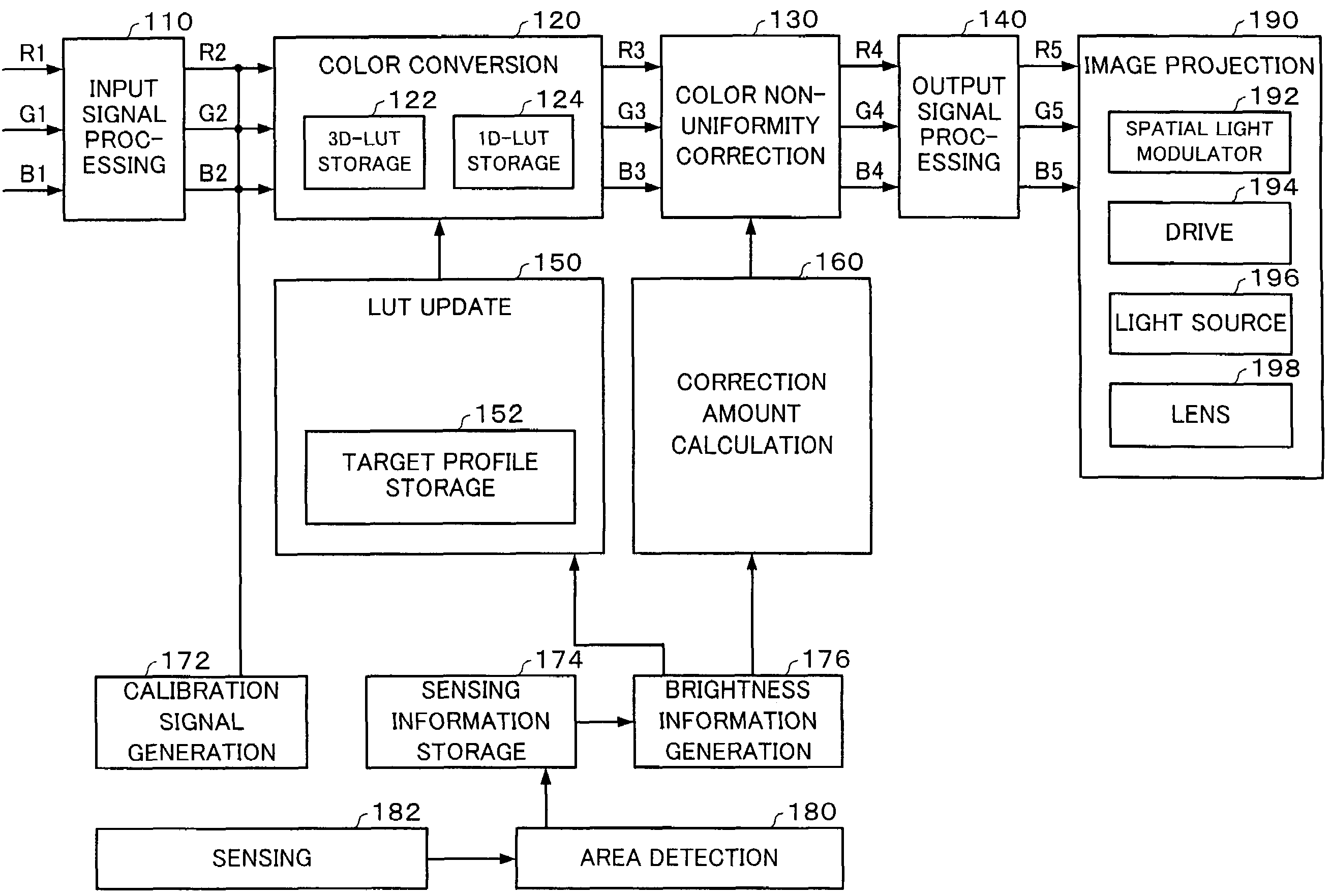
[0009]The present invention was devised in the light of the above-described problems, and may provide an image processing system, a projector, a program, an information storage medium, and an image processing method that enable a more appropriate correction of color non-uniformity due to deterioration with time.
[0067]Since the present invention enables the image processing system or the like to detect which of the target areas is insufficiently bright, by dividing the image display area into a plurality of target areas and detecting the average brightness index value for each of those target areas, it is possible to detect whether there is deterioration in part of the image.
[0068]The image processing system or the like can correct color non-uniformity due to deterioration with time as appropriate, by obtaining a correction amount for each of the divided target areas and correcting color non-uniformity for each of the divided target areas.
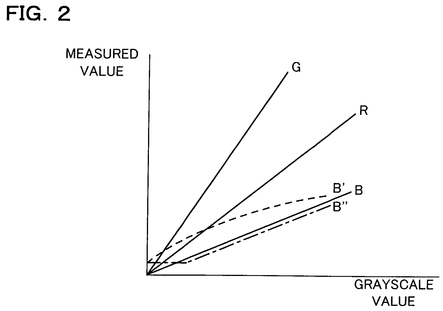
[0084]Since this enables the image processing system or the like to obtain an average brightness index value of the image that is actually being displayed for each grayscale value, and also determine any difference in the average brightness index value for each grayscale value, it makes it possible to provide more appropriate correction of color non-uniformity due to deterioration with time.
[0087]Since this enables an approximation to the input-output characteristic in the state in which there is no deterioration, by calculating correction amounts so that the input-output characteristic approaches the state in which there is no color non-uniformity, it makes it possible to provide more appropriate correction of color non-uniformity.

Problems solved by technology

When an image is displayed for a long time by an image display device such as a projector, color non-uniformity (including color non-uniformity due to luminance non-uniformity) is created in the image and thus the image gradually deteriorates.
In such a case, the original display effect could be lost due to deterioration of components such as the liquid-crystal panel or a polarized plate during projection over a long period of time, which could generate color non-uniformity in the image.
However, color non-uniformity deterioration does not include only deterioration of the entire image; it also includes deterioration of parts of the image.
Variations in light quantity are particularly likely to occur in liquid-crystal light valves and polarized plates within the paths of powerful blue light and highly energy-intensive (large light quantity) green light.
Such deterioration in the liquid-crystal light valves or polarized plates leads not only to deterioration the entire polarized plates, but also to deterioration of parts thereof.
As a result, not only the entire image, but also parts of that image could deteriorate.
In such a case, it would be difficult to correct the image as appropriate with the method disclosed in Japanese Patent Application Laid-Open No. 2002-140060, wherein information on the operating time of the display means.

Method used


Image

  • Image processing system, projector, program, information storage medium, and image processing method
  • Image processing system, projector, program, information storage medium, and image processing method
  • Image processing system, projector, program, information storage medium, and image processing method

Examples


Embodiment Construction

[0095]In the description below, the present invention is applied to a projector having an image processing system, by way of example, with reference to the accompanying figures. Note that the embodiments described below do not in any way limit the scope of the present invention as laid out in the claims herein. In addition, the entirety of the configuration described with reference to these embodiments is not limited to being essential structural components of the present invention.

Description of Overall System

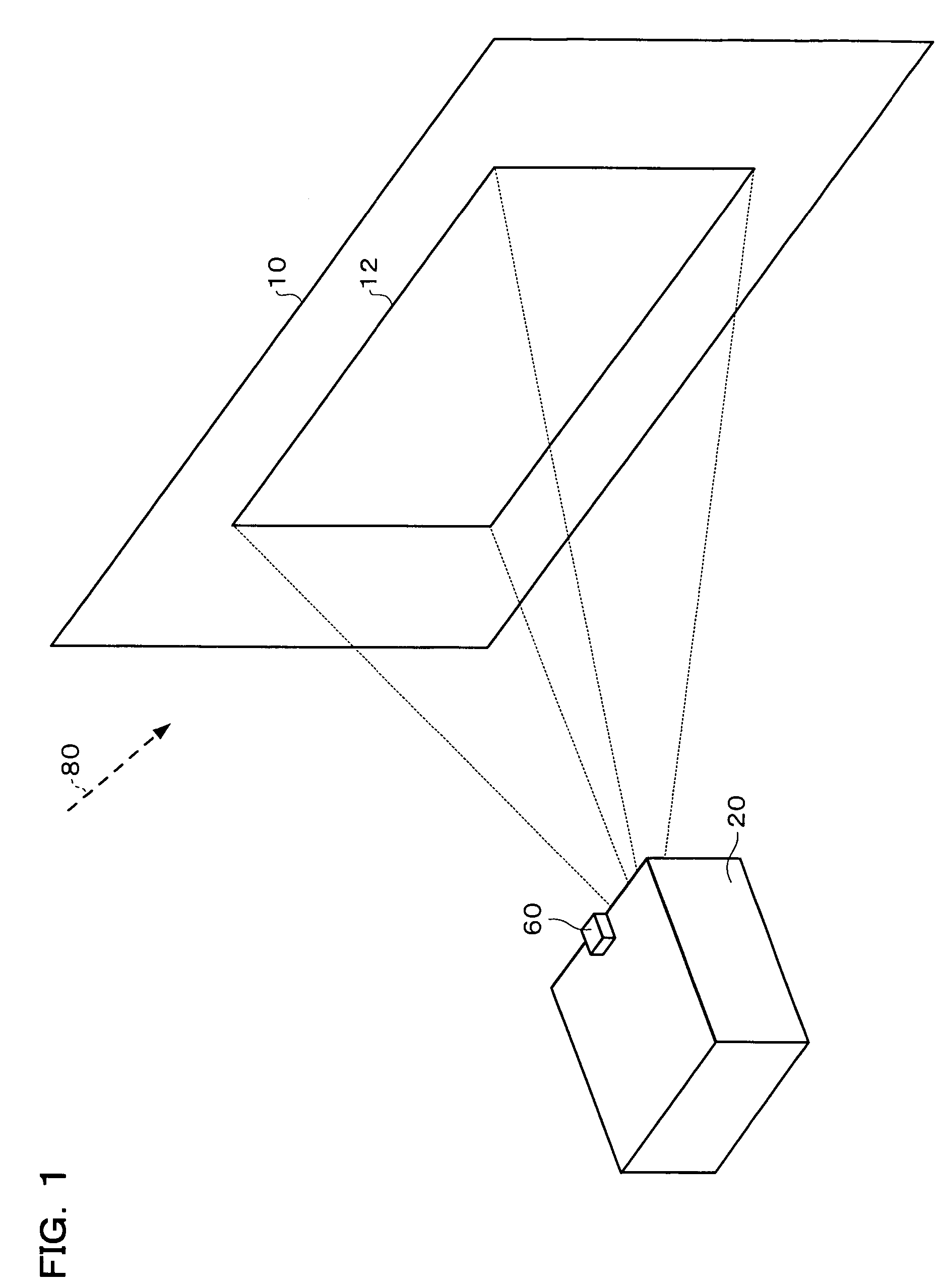
[0096]A schematic view of an entire image processing system in accordance with an example of this embodiment is shown in FIG. 1.

[0097]A projector 20 projects an image towards a screen area 10. This causes the formation of a projection area 12 that is an image display area in the screen area 10.

[0098]If an image display device such as the projector 20 is used for displaying an image a long period of time in this manner, time-related deterioration in components such as the optic...


PUM


Abstract

In order to provide an image processing system that can correct color non-uniformity due to deterioration with time in a more appropriate manner, a projector is provided with an image projection section which displays a calibration image; a sensing section which senses the displayed calibration image; an area detection section which detects an image display area based on sensing information, and also divides the image display area into a plurality of target areas; a brightness information generation section which generates brightness information which indicates an average brightness index value within each of the target areas that have been divided by the area detection section, based on the sensing information; a correction amount calculation section which calculates a correction amount for input-output characteristic data from each of the target areas, based on the brightness information; and a color non-uniformity correction section which corrects color non-uniformity of the image, based on input-output characteristic data that has been corrected based on the correction amount.

Description

[0001]Japanese Patent Application No. 2003-14666, filed on Jan. 23, 2003, is hereby incorporated by reference in its entirety.BACKGROUND OF THE INVENTION[0002]The present invention relates to an image processing system, a projector, a program, an information storage medium, and an image processing method that correct color non-uniformity in images.[0003]When an image is displayed for a long time by an image display device such as a projector, color non-uniformity (including color non-uniformity due to luminance non-uniformity) is created in the image and thus the image gradually deteriorates.[0004]This could happen when a projector is used to display an image continuously on a screen in a store or exhibition hall, for example. In such a case, the original display effect could be lost due to deterioration of components such as the liquid-crystal panel or a polarized plate during projection over a long period of time, which could generate color non-uniformity in the image.[0005]As an ...

Claims


Application Information

Patent Timeline
IPC IPC(8): G09G5/10G06T1/00G09G3/20G09G5/00G09G5/02H04N1/46H04N1/60H04N9/31H04N9/64H04N9/73H04N17/04
CPCH04N9/73H04N9/3182A61B17/06A61B2017/06052
Inventor MATSUDA, HIDEKI
Owner SEIKO EPSON CORP
Learn More