

Luminescent nanoparticles and methods for their preparation
a technology of nanoparticles and light-emitting particles, which is applied in the field of light-emitting nanoparticles and methods for their preparation, can solve the problems of bare nanocrystals, i.e., nanocrystal cores, and the destruction of shell overcoating methodologies, which have, to date, been relatively rudimentary
- Summary
- Abstract
- Description
- Claims
- Application Information
AI Technical Summary
Benefits of technology
Problems solved by technology
Method used
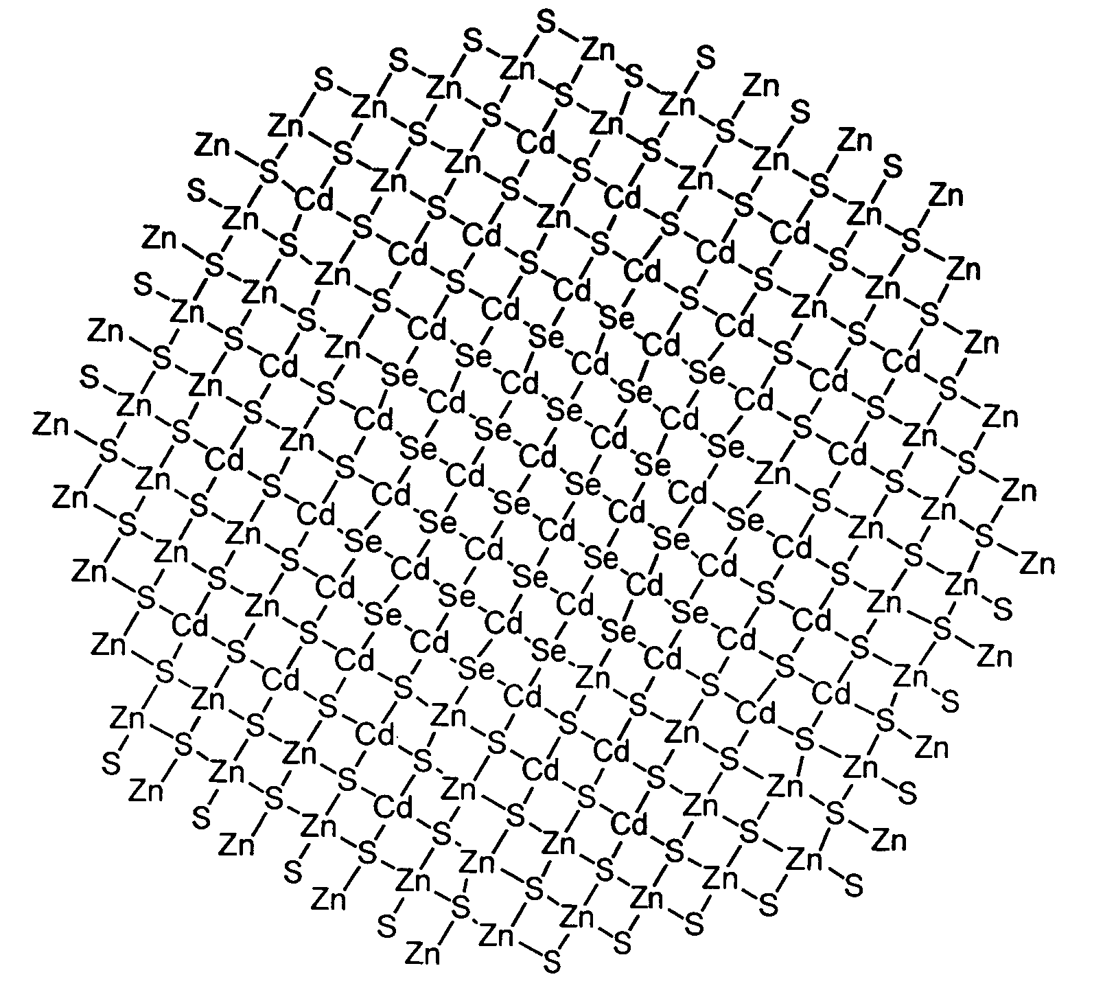
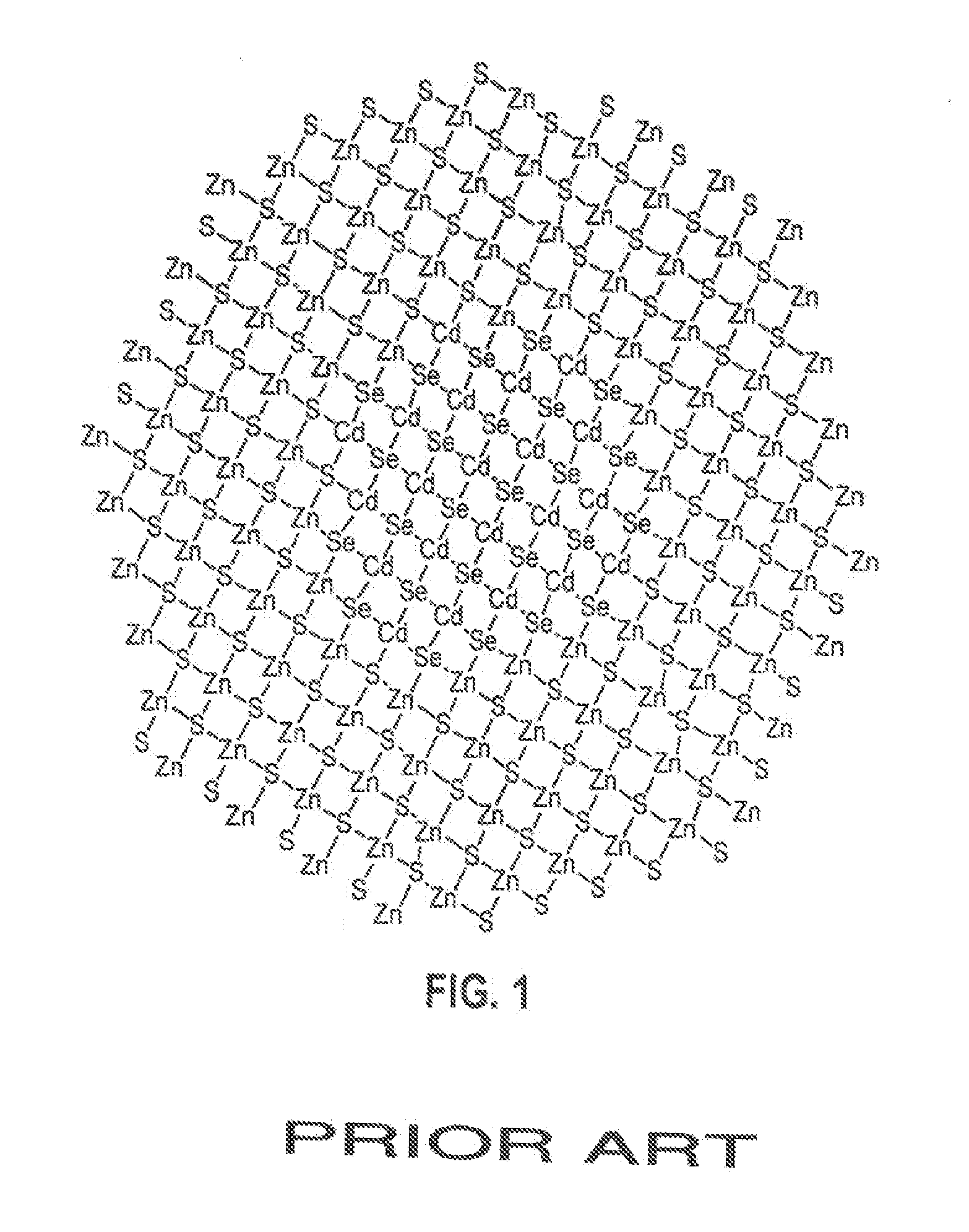
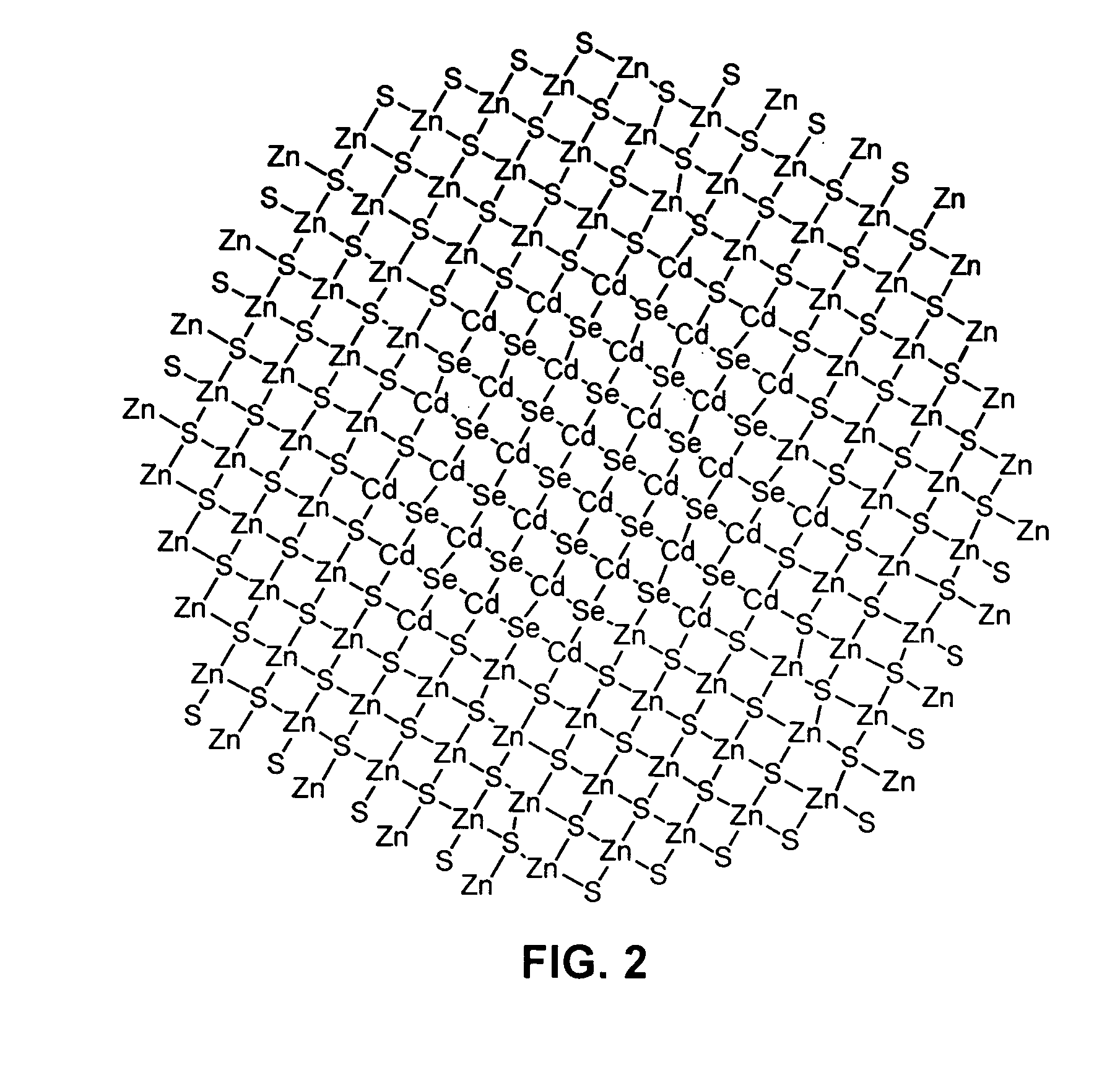
Image

Examples
example 1
Preparation of Core-Shell Nanocrystals Using Added Dimethylcadmium
[0074]Tri-n-octylphosphine oxide (TOPO, 30 g) was degassed for 1 hr under vacuum at 180° C. in a 3-neck round bottom flask containing a stir bar on a heating mantle, and equipped with a bump trap and a thermocouple (and temperature controller). The molten reaction was placed under a dry N2 atmosphere and heated to 350° C. Inside an inert atmosphere glove box, Se (360 mg) was combined with dimethylcadmium (230 μL) in tri-n-octylphosphine (TOP, 20 mL). In a single rapid injection, the TOP solution was added to the hot TOPO pot after removing the heat from the reaction. After injection, the temperature fell to 265° C., and it was heated to 290° C. An increasing temperature ramp of +1° C. / hr was applied to the reaction for 6.5 hr until the emission maximum of the particles reached 608 nm. The reaction was cooled to 100° C. Decylamine (11 mL) was added via syringe and heating maintained overnight.
[0075]Using a similar reac...
example 2
Preparation of Core-Shell Nanocrystals Using Added Cadmium Diacetate
[0077]Nanocrystals were prepared in a manner similar to that described Example 1, except that the dimethylcadmium / TOP solution in the shell overcoating procedure was replaced with a cadmium di-acetate / TOP solution. A 0.25 mL of a 0.67 M solution of the cadmium di-acetate / TOP solution was used. The resultant overcoated nanocrystals displayed a similar shell thickness as those prepared in Example 1. Photostabilities were also comparable.
example 3
Preparation of Core-Shell Nanocrystals Using Super-Abundances of Shell Precursors as Additives
[0078]The core reaction was carried out as described in Example 1, with the exception that the reaction was stopped when the peak emission of the nanoparticles reached 622 nm rather than 608 nm. No dimethylcadmium or cadmium di-acetate was added to the shell reaction. The shell stock solution contained TOP (6.3 g), diethylzinc (206 mg), and bis(trimethylsilyl)sulfide (450 mg). Shell reactions were conducted containing the S:Zn precursor ratios indicated in FIG. 5. In addition, a control reaction was conducted in which a 1:1 molar ratio of S and Zn precursors was used. Shell thickness and particle morphology were evaluated for all S:Zn precursor ratios. A dramatic difference was found in the brightness of the particles: emission quantum yields of 0.76 and 0.22 were measured for the 1.5:1 S precursor:Zn precursor molar ratio reaction and the control reaction, respectively (see FIG. 5)
PUM
| Property | Measurement | Unit |
|---|---|---|
| temperature | aaaaa | aaaaa |
| diameters | aaaaa | aaaaa |
| diameter | aaaaa | aaaaa |
Abstract
Description
Claims
Application Information