Optical fiber sensors for harsh environments

a fiber optic sensor and harsh environment technology, applied in the field of optical sensors, can solve the problems of observing interference changing the cavity, corresponding changes in the interference pattern between the two reflections, etc., and achieve the effect of reducing or eliminating the temperature dependence of the sensor

Inactive Publication Date: 2007-02-06
VIRGINIA TECH INTPROP INC
View PDF27 Cites 77 Cited by
  • Summary
  • Abstract
  • Description
  • Claims
  • Application Information

AI Technical Summary

Benefits of technology

[0010]In one aspect of the invention, bonds between the ferrule and fiber and diaphragm and ferrule are formed by welding the ferrule to the fiber and the diaphragm to the ferrule. The welding may be accomplished by any means (e.g., electric arc), but is preferably accomplished with a laser. In some embodiments, the entire ferrule is bonded to the fiber along the entire length of portion of the fiber that is within the ferrule. In other embodiments, particularly those embodiments in which there is a mismatch in the coefficients of thermal expansion of the ferrule and fiber (which may result from the presence of dopants in the fiber but not in the ferrule, or differences in the types or amounts of dopants in the fiber and ferrule), only a small portion of the fiber is welded to the ferrule to provide for small amounts of relative movement between the fiber and ferrule in the non-welded areas to accommodate movement due to thermal expansion and contraction. Using welding has the added advantage of driving air out of the cavity between the ferrule and diaphragm, which decreases the temperature dependence of the sensor.
[0012]In still another aspect of the invention, a small piece of optical fiber is spliced to an end of the main fiber to reduce or eliminate the temperature dependence of the sensor. The ferrule is laser welded to the main optical fiber, while the small piece of optical fiber is not attached to the ferrule. When the sensor is subjected to high temperatures, any air remaining in recess between the diaphragm and ferrule will expand, causing the diaphragm to deflect outward. The outward deflection of the diaphragm changes the length of the Fabry-Perot cavity between the end of the fiber and the diaphragm. The small piece of optical fiber is chosen to have a coefficient of thermal expansion such that the small piece of optical fiber will expand in an amount equal a distance that the diaphragm will deflect at elevated temperatures. Any differences between the coefficients of thermal expansion of the ferrule and the main optical fiber can also be compensated for by the small piece of optical fiber. Thus, for example, if the ferrule has a coefficient of thermal expansion that is greater than that of the main fiber, the small piece of optical fiber is chosen to have a coefficient of thermal expansion greater than both the ferrule and the main fiber. This allows the small piece of optical fiber to expand a greater amount than the ferrule in the presence of an elevated temperature to balance the lower amount of thermal expansion of the main fiber relative to the ferrule.

Problems solved by technology

If the coherence length of the light source exceeds twice the length of the cavity, observable interference between the two reflections occurs.
Deflections of the diaphragm due to a pressure applied to the diaphragm result in changes to the cavity length, which result in corresponding changes in the interference pattern from the two reflections.
However, the use of viscoelastic materials such as epoxies subjects the sensor to time dependent changes, thereby compromising the reproducibility and operation of the sensor.
In addition, the use of viscoelastic materials increases the temperature dependence of the sensor.
Applicants have experimented with such a procedure but the mechanical bond between the collapsed portion of the capillary tube and the fiber that results from this process has proven unsatisfactory.
The techniques disclosed in WO 99 / 60341 are an improvement over the use of epoxies, but are not ideal.

Method used


Image

  • Optical fiber sensors for harsh environments
  • Optical fiber sensors for harsh environments
  • Optical fiber sensors for harsh environments

Examples


Embodiment Construction

[0020]The present invention will be discussed with reference to preferred embodiments of diaphragm sensors. Specific details are set forth in order to provide a thorough understanding of the present invention. The preferred embodiments discussed herein should not be understood to limit the invention. Furthermore, for ease of understanding, certain method steps are delineated as separate steps; however, these steps should not be construed as necessarily distinct nor order dependent in their performance.

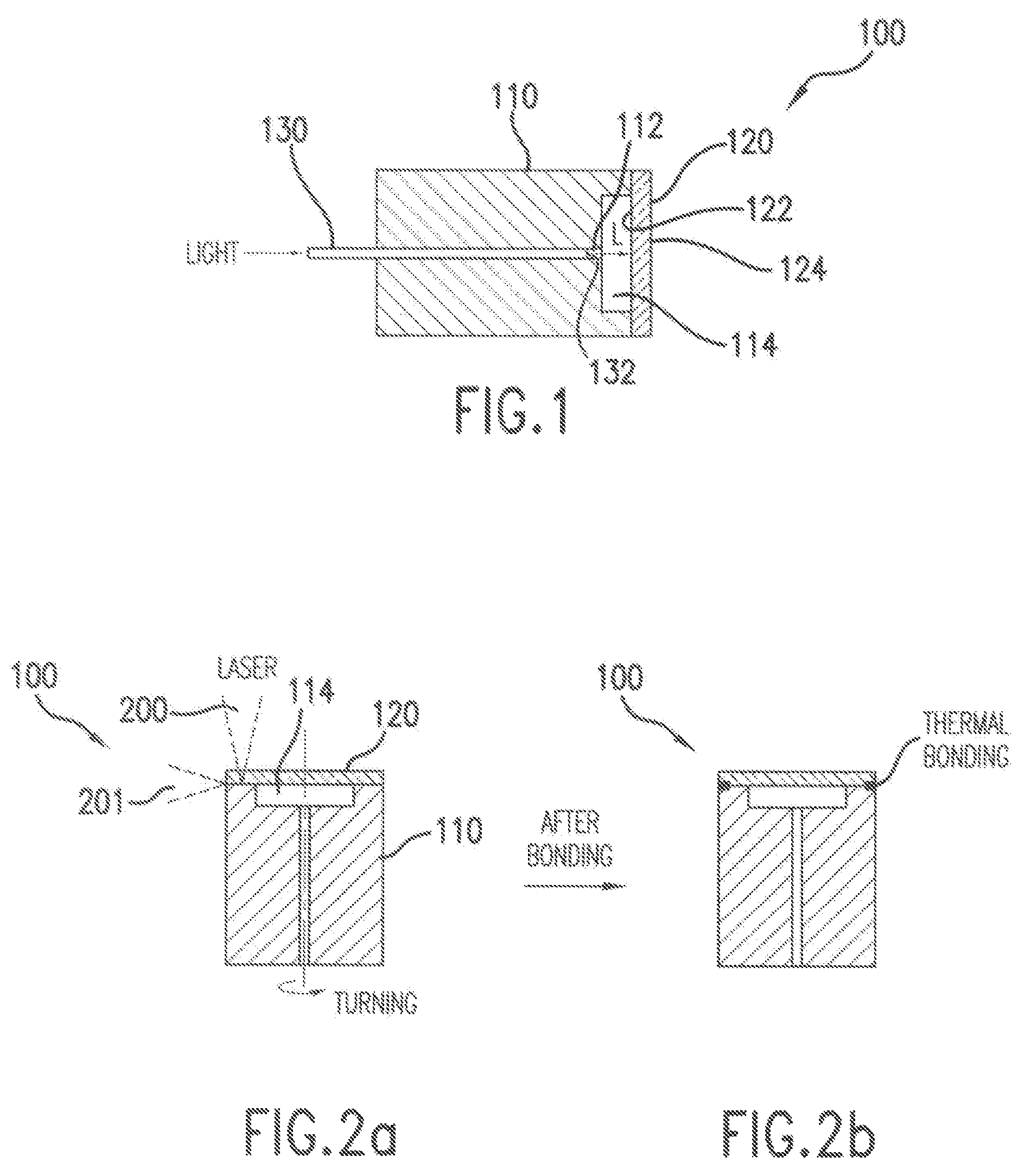
[0021]A cross sectional view of a diaphragm sensor 100 according to one embodiment of the invention is illustrated in FIG. 1. The sensor includes a ferrule 110 in which a central bore 112 is formed. A pit, or recess, 114 is formed in one end of the ferrule 110. A diaphragm 120 is attached to the ferrule 110 to cover the pit 114. An optical fiber 130 is disposed within the central bore 112. The ferrule 110, diaphragm 120 and optical fiber 130 may be formed from a wide variety of materia...


PUM


Abstract

A diaphragm optic sensor comprises a ferrule including a bore having an optical fiber disposed therein and a diaphragm attached to the ferrule, the diaphragm being spaced apart from the ferrule to form a Fabry-Perot cavity. The cavity is formed by creating a pit in the ferrule or in the diaphragm. The components of the sensor are preferably welded together, preferably by laser welding. In some embodiments, the entire ferrule is bonded to the fiber along the entire length of the fiber within the ferrule; in other embodiments, only a portion of the ferrule is welded to the fiber. A partial vacuum is preferably formed in the pit. A small piece of optical fiber with a coefficient of thermal expansion chosen to compensate for mismatches between the main fiber and ferrule may be spliced to the end of the fiber.

Description

[0001]This invention was partially made with Government support under grant number DEFC3601G01050 awarded by the U.S. Department of Energy. The Government may have certain rights in the invention.BACKGROUND OF THE INVENTION[0002]1. Field of the Invention[0003]The invention relates to optical sensors generally, and more particularly to Fabry-Perot cavity sensors.[0004]2. Discussion of the Background[0005]Optical sensors are used in a wide variety of applications. They offer advantages as compared to other types of sensors, including small size, immunity to electromagnetic interference (EMI), extreme stability, long life, high temperature operation, and low cost. They are especially useful in harsh environments, including high temperature, high pressure environments.[0006]One type of optical sensor is the diaphragm-based Fabry-Perot sensor. In such sensors, a Fabry-Perot cavity is formed between an end of an optical fiber and a reflective diaphragm. Two reflections occur in these sens...

Claims


Application Information

Patent Timeline
Patent Type & Authority Patents(United States)
IPC IPC(8): G01B9/02G02B6/00
CPCG01D5/266G01L9/0079G01K11/3206G01D5/268G01D5/35312
Inventor XU, JUNCHENGWANG, ANBO
Owner VIRGINIA TECH INTPROP INC
Why Eureka
Try Eureka