Chiller with improved product distribution

a technology of product distribution and chiller, which is applied in the field of chillers, can solve the problems of birds falling behind, wasting a longer time in the tank, and a greater risk of some birds, so as to reduce the temperature of birds, increase the temperature transfer rate, and handle more birds

Active Publication Date: 2007-02-13
MORRIS & ASSOCS
View PDF30 Cites 10 Cited by
  • Summary
  • Abstract
  • Description
  • Claims
  • Application Information

AI Technical Summary

Benefits of technology

[0014]Briefly described, the present invention comprises an improved poultry chiller with a rotary auger for efficiently reducing the temperature of birds that have been processed for human consumption. The chiller has the ability to handle more birds by increasing the rate of temperature transfer from the birds. The invention tends to reduce the extensive accumulation of birds on the pulling side of the chiller tank that has the hazard of causing bird cross-over from one flight of the auger to the trailing flight of the auger. The invention provides tighter control of chilling time for each bird and better management of feed rate to downstream processing.
[0016]In order to avoid the excessive accumulation of birds on the pulling side of the tank, nozzles are positioned at the side wall of the tank on the pulling side of the auger shaft and are oriented for moving streams of water laterally into the water in the tank. The streams of water are directed from the pulling side of the tank, below the auger shaft, generally parallel to the surfaces of the auger, and toward the dead side of the tank. The streams of water tend to keep birds away from the pulling side of the tank and tend to remove some of the birds from the masses of buoyant birds on the pulling side of the tank, by moving the birds below the auger shaft and toward the dead side of the tank. This spreads the birds toward the dead side of the tank where there are fewer birds, thereby increasing the rate of cooling of the birds on both sides of the tank.
[0017]The tank of the chiller is more than half cylindrical so as to have its cylindrical shape continue partially around the upper half of the auger. This avoids the creation of the triangular shaped gaps 26 between the flights of the auger and the side of the tank as shown in FIG. 1, and allows the level of water in the tank to be raised. The additional volume of water in the tank allows more birds to be processed through the tank.
[0018]The reduction of the accumulation of masses of the birds on one side of the auger spreads the birds from one another and increases the rate of heat transfer from the birds, and allows more birds to be accommodated in the chiller. This also allows the water level to be raised without increased hazard of the birds moving over the auger shaft, thereby allowing even more birds to be accommodated in the chiller.
[0019]Thus, it is an object of this invention to provide a chiller with improved bird distribution in the chiller tank, and to increase the rate of heat transfer from the birds while reducing the hazard of cross-over of the birds from one auger flight to the following auger flight.
[0020]Another object of this invention is to provide a more efficient chiller for oven-ready birds, that has an increased production capacity for chilling the products without enlarging the footprint of the chiller in the work space.

Problems solved by technology

This results in some of the birds falling behind by one auger segment and spending a longer time than necessary in the tank.
But if high water is used in the chiller tank of FIG. 2 as shown by water level 31, there is a hazard that some of the birds 22 that accumulate on the pulling side of the tank will float over the auger shaft 28.
This results in the birds falling behind to the next accumulation of birds and the birds remain in the chiller an additional 3 to 5 minutes, which is longer than the time required for chilling the bird.
Another problem in the birds falling behind to a following auger flight in a prior art bird chiller is created when the entire poultry processing line is progressively shut down for a work break.
Even if the operation of the chiller is not interrupted for a work break, the non-uniform delivery of birds from the chiller reduces the efficiency of the following processing line.

Method used


Image

  • Chiller with improved product distribution
  • Chiller with improved product distribution
  • Chiller with improved product distribution

Examples


Embodiment Construction

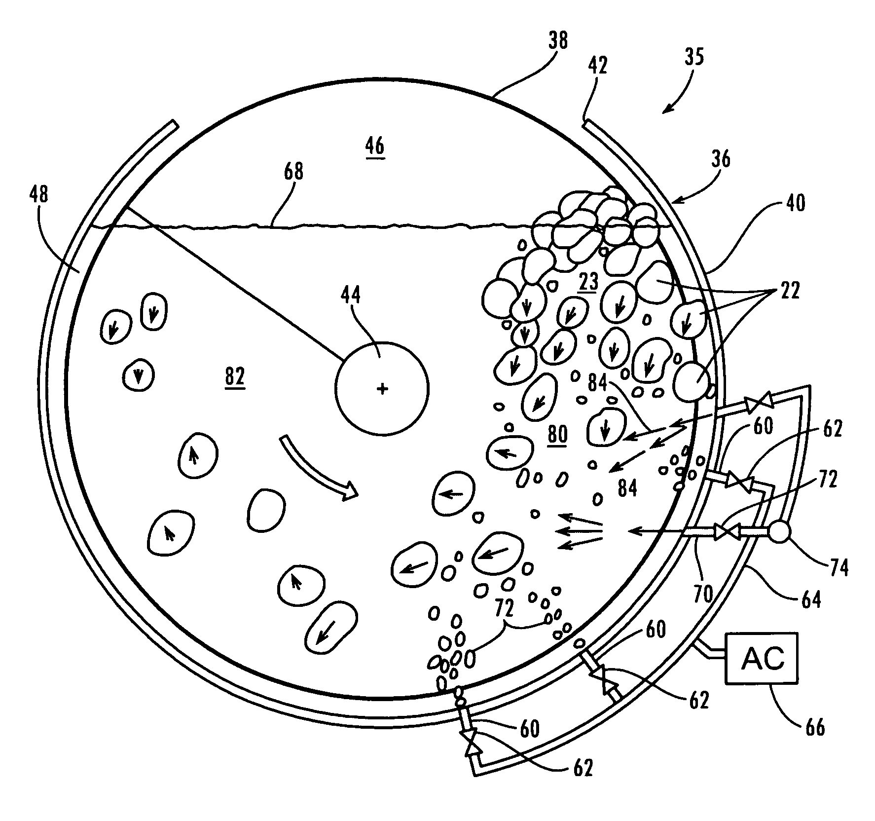
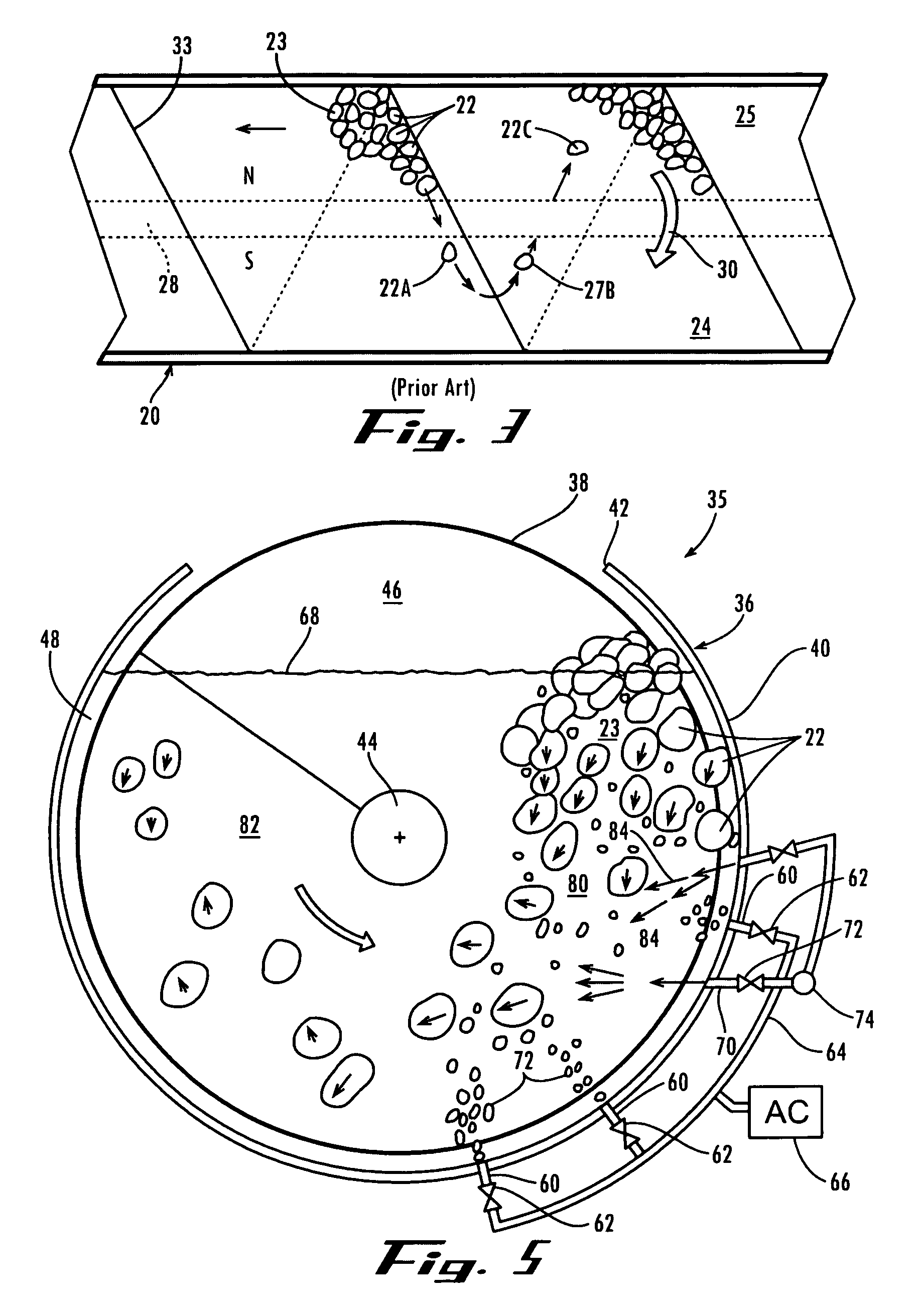
[0028]Referring now in more detail to the drawings, in which like numerals indicate like parts throughout the several views, FIGS. 4 and 5 illustrate a poultry chiller 35 having an elongated tank 36 and an auger 38 in the tank. The tank has a semi-cylindrical side wall 40 that has an opening 42 at its upper portion. In the embodiment shown, the semi-cylindrical side wall extends approximately 290° about the auger 38, with the tank opening 42 extending the remaining approximately 70°. Other degrees of tank extensions about the auger may be used as may be desired. The helical auger 38 is centrally located within the semi-cylindrical side wall 40 with the auger shaft 44 being substantially coextensive with respect to the center line of the semi-cylindrical side wall 40 of the tank. The auger includes a helical blade 46 formed in several flights (not shown) that are supported by and surround auger shaft 44, with the auger blade extending out closely adjacent the semi-cylindrical side wa...


PUM


Abstract

The chiller includes a semi-cylindrical tank (36) that conforms to the perimeter of its auger (38) so that the water can be raised to a water level (68) high above the auger shaft (44). Streams of water (84) are directed from the pulling side (80) across the lower portion of the tank beneath the auger shaft (44) to the dead side 82 of the tank at intervals along the tank so as to disperse the lower portion of the masses (23) of buoyant birds (22) from the more crowded pulling side (80) of the tank, beneath the auger shaft (44) toward the more vacant dead side (82) of the tank, thereby distributing the products more evenly throughout the tank and causing more water turbulence in the tank, thereby increasing the rate of heat transfer from the birds and avoiding having the birds cross over the auger shaft moving backward in chiller into a following flight of the auger.

Description

FIELD OF THE INVENTION[0001]This invention involves chillers for reducing the temperature of whole birds that have been defeathered, eviscerated and otherwise prepared for human consumption. More particularly, the invention concerns an auger type poultry chiller in which the massing or “clumping” of birds on one side of the auger tank and the movement of the birds over the auger shaft are reduced.BACKGROUND OF THE INVENTION[0002]Food chillers, such as the auger type poultry chillers, are used in poultry processing plants for reducing the temperature of the birds after the birds have come off the processing line and have been defeathered, eviscerated and otherwise have been made oven-ready, for packaging and shipment to the consumers.[0003]A typical auger type poultry chiller includes an elongated, half-cylindrical tank having a rotary auger placed therein. Water is placed in the tank and is recirculated through a cooling system such as a refrigeration system, with the water directed...

Claims


Application Information

Patent Timeline
Patent Type & Authority Patents(United States)
IPC IPC(8): F25D17/06
CPCA22C21/00F25D13/065A23B4/06F25D2400/28
Inventor MORRIS, III, WILLIAM F.WRIGHT, TERRY A.SHELL, JOHN P.CATHEY, ROBERT E.
Owner MORRIS & ASSOCS
Why Eureka
Try Eureka