Control apparatus for dry sump type internal combustion engine

a control apparatus and internal combustion engine technology, applied in the direction of machines/engines, electric control, auxiliary lubrication, etc., can solve the problems of increasing pump mechanical loss and pump work, and increasing power consumption with an increase in engine speed. , to achieve the effect of reducing nox density, increasing energy consumption, and increasing ventilation

Active Publication Date: 2007-02-13
TOYOTA JIDOSHA KK +1
View PDF16 Cites 25 Cited by
  • Summary
  • Abstract
  • Description
  • Claims
  • Application Information

AI Technical Summary

Benefits of technology

[0020]The first aspect of the present invention controls the increase in the energy consumption in a high rotation speed region and sufficiently reduces the NOx density in a low rotation speed region by providing the crank chamber with increased ventilation, thereby effectively controlling the deterioration of oil. In other words, the present invention makes it possible to establish a system that is capable of producing the effects of scavenge pump drive in a low rotation speed region, which is an actual normal operation region for the internal combustion engine.
[0021]The second aspect of the present invention makes adjustments so that the discharge volume ratio used in a high rotation speed region is lower than the discharge volume ratio used in a low rotation speed region. Therefore, the present invention makes it possible to control the increase in the energy consumption in a high rotation speed region and sufficiently reduce the NOx density in a low rotation speed region by providing the crank chamber with increased ventilation, thereby effectively controlling the deterioration of oil.

Problems solved by technology

When, in the above conventional apparatus, the feed pump's discharge volume (rotation speed) increases with an increase in the engine speed, thereby increasing the electric scavenge pump's discharge volume (rotation speed), the pump drive loss increases (the pump mechanical loss and pump work increase).
As a result, the power consumption increases with an increase in the engine speed.

Method used


Image

  • Control apparatus for dry sump type internal combustion engine
  • Control apparatus for dry sump type internal combustion engine
  • Control apparatus for dry sump type internal combustion engine

Examples


first embodiment

[Configuration of First Embodiment]

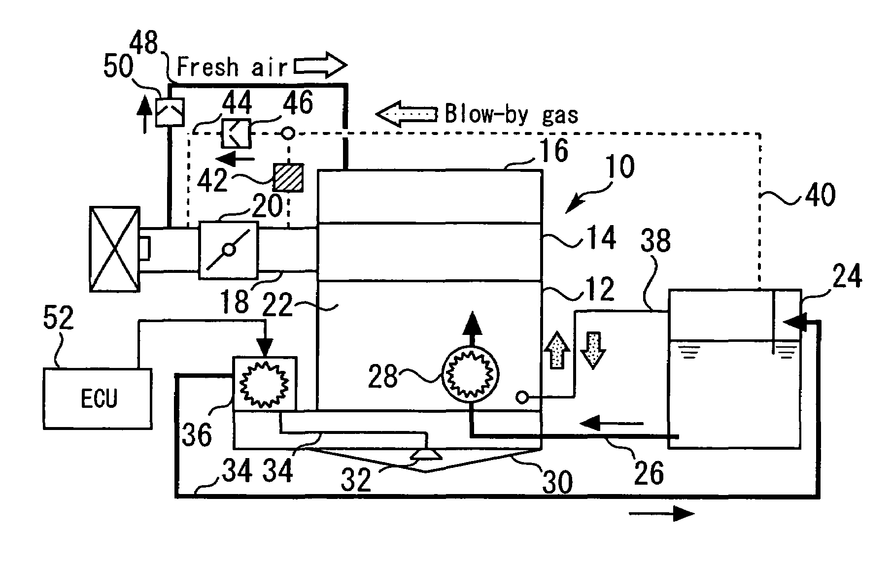
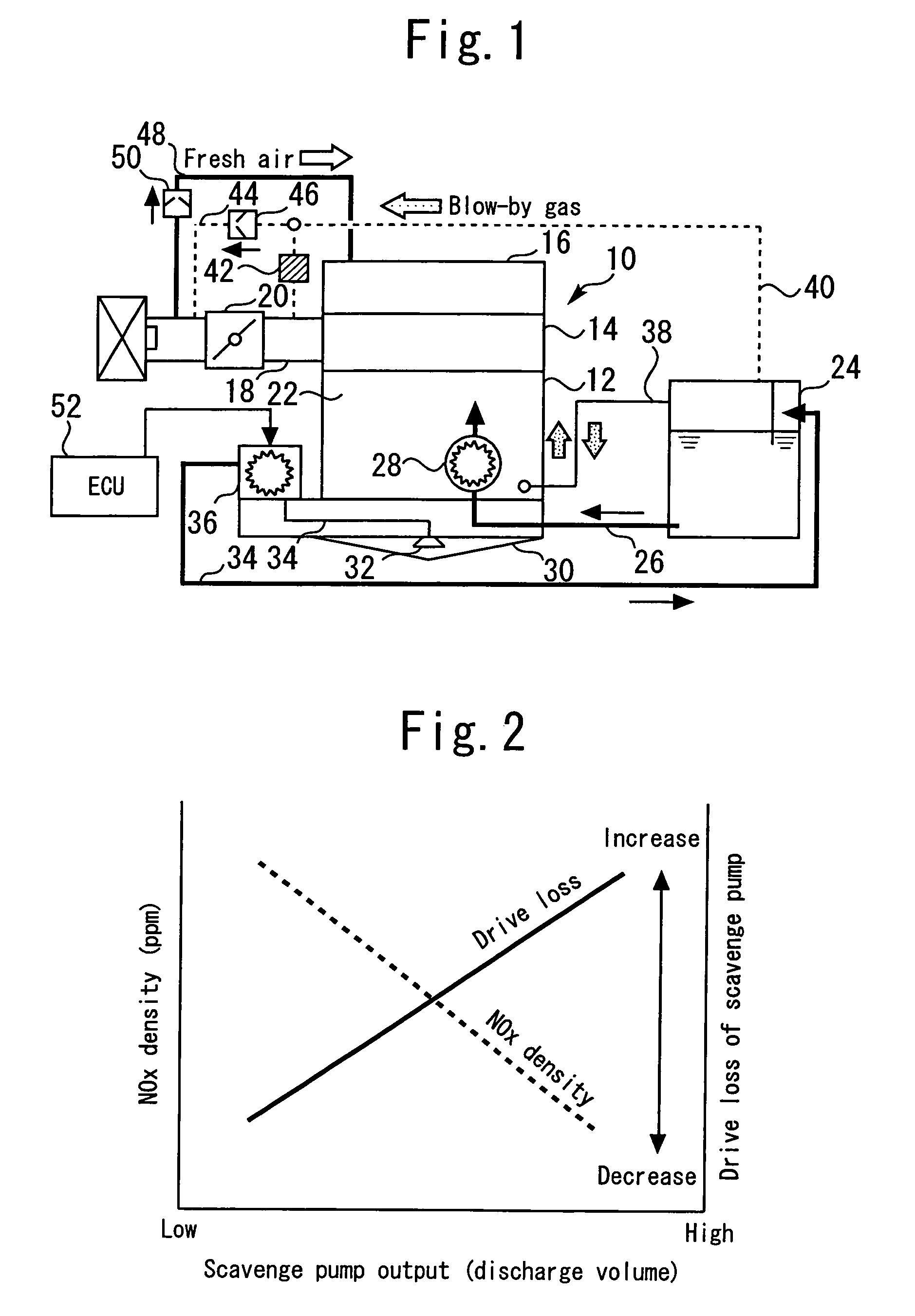
[0031]FIG. 1 illustrates the configuration of a dry sump type internal combustion engine according to a first embodiment of the present invention. The internal combustion engine 10 shown in FIG. 1 includes a cylinder block 12. A cylinder head 14 is mounted on the top of the cylinder block 12. A head cover 16 is mounted on the top of the cylinder head 14. The cylinder head 14 communicates with an intake path 18. The intake path 18 is provided with a throttle body 20, which is positioned downstream of an air cleaner.

[0032]A crank chamber 22 is formed within the cylinder block 12. The crank chamber 22 is positioned below a piston (not shown). The system according to the present embodiment includes an oil tank 24, which stores the oil that is to be supplied to various sections of the internal combustion engine 10. The bottom of the oil tank 24 communicates with one end of an oil supply pipe 26. The remaining end of the oil supply pipe 26 communicates w...

second embodiment

[0064]A second embodiment of the present invention will now be described with reference to FIG. 8.

[0065]The system according to the present embodiment is configured the same as the first embodiment except that a NOx density sensor is incorporated to detect the NOx density in the crank chamber 22. The first embodiment, which has been described earlier, changes the S / F ratio in accordance with the engine speed. The system according to the present embodiment changes the S / F ratio in accordance with the NOx density in the crank chamber 22 as well as the engine speed.

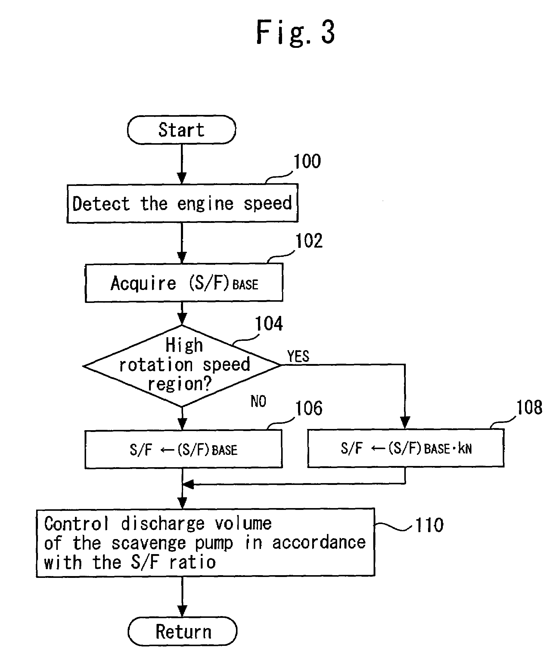
[0066]FIG. 8 is a flowchart illustrating a routine that the ECU 52 according to the present embodiment executes to implement the above functionality. When the present embodiment is described with reference to FIG. 8, steps identical with those described with reference to FIG. 3 for the first embodiment are designated by the same reference numerals as their counterparts and omitted from the description or briefly described. I...


PUM


Abstract

A feed pump 28 that is driven by the axial torque of an internal combustion engine 10 is installed. An electric scavenge pump 36 is installed. A base value for the ratio (S / F ratio) between the discharge volume of the scavenge pump 36 and feed pump 28 is calculated. The base value is corrected so that the S / F ratio is lower in a region where the engine speed is high than in a region where the engine speed is low. The discharge volume of the scavenge pump 36 is controlled in accordance with the S / F ratio that is corrected in the above manner.

Description

[0001]This is a Continuation of Application No. PCT / JP2005 / 011194 filed Jun. 13, 2005, which claims the benefit of Japanese Patent Application No. 2004-183536 filed Jun. 22, 2004. The entire disclosure of the prior applications is hereby incorporated by reference herein in its entirety.TECHNICAL FIELD[0002]The present invention relates to a control apparatus for a dry sump type internal combustion engine, and more particularly to a control apparatus for a dry sump type internal combustion engine that includes a scavenge pump whose discharge volume can be changed without depending on the engine speed.BACKGROUND ART[0003]A conventional dry sump type internal combustion engine control apparatus is disclosed, for instance, by Japanese Patent Laid-Open No. 2000-337119. This control apparatus includes an electric feed pump for supplying oil from an oil tank, which is positioned outside a crank chamber, into the crank chamber. This control apparatus also includes an electric scavenge pump ...

Claims


Application Information

Patent Timeline
Patent Type & Authority Patents(United States)
IPC IPC(8): F01M1/02F01M1/12F01M1/16F01M11/10F01M13/00F01M13/02F02D41/14F16N29/00
CPCF01M1/12F01M1/16F01M11/10F02D41/146F01M2001/126F01M2013/0077F01M2013/026F01M2001/123
Inventor SUZUKI, TAKAOUSUI, HIDENORI
Owner TOYOTA JIDOSHA KK
Why Eureka
Try Eureka