
Fan type chemicals diffusing device

a chemical and fan-type technology, applied in the direction of machines/engines, biocide, separation processes, etc., can solve the problems of complex structure, large size of the apparatus, complex structure of the apparatus, etc., to prevent any other damage, prevent bloodsucking, biting or eating behavior, and control growth

Inactive Publication Date: 2007-02-13
FUMAKILLA LTD
View PDF40 Cites 72 Cited by
  • Summary
  • Abstract
  • Description
  • Claims
  • Application Information

AI Technical Summary

Benefits of technology

The present invention provides a fan type chemical diffusing apparatus for repelling and excluding noxious or harmful insects, which includes an active ingredient impregnated body or mass and a fan type blower powered by a motor. The apparatus has a unique design that allows for efficient utilization of motor driving energy to volatilize the active ingredient and prevent damage or harm to the insect. The fan type blower has a specific air resistance, size, and weight, which are selected to optimize the battery life and motor performance. The invention also provides a fan type debugging apparatus for repelling and excluding a noxious or harmful insect, which includes an active ingredient impregnated body or mass and a fan type blower powered by a motor. The apparatus has a unique design that allows for efficient utilization of motor driving energy to volatilize the active ingredient and prevent damage or harm to the insect. The invention also provides a method for effectively balancing wind resistance and volatilization of the active ingredient.

Problems solved by technology

As a result, it is forced to be complex in structure and makes the apparatus large in size.
The requirement that the active ingredient impregnated body and the fan be arranged to efficiently send air into, through and out of the active ingredient impregnated body tends to make the apparatus structure complex and large in size.
If the apparatus is to be powered by a battery, providing a space for accommodating the battery in the apparatus makes the apparatus even more complex and larger in size.
However, many problems still remain unresolved, for example, as regards an unsatisfactory durability (e.g., brittleness) of the fan which must be made by forming, a limited impregnable amount (small amount) of an active ingredient and, if the fan is of replacement type, the time, labor and cost entailed for replacement, which may make the apparatus poor in utility and serviceability.
The first type debugging apparatus seems to lack concreteness and seems to have many problems to be resolved for practical use.
The second type debugging apparatus is technologically concrete and practical but if ever practiced seems to lack flexibility.
But, the idea of requiring it to be shaped so as to reduce wind resistance as much as possible was found much questionable.
This is a loss in wind force and in other words a loss in driving energy.
In contrast, excessively increasing air resistance would reduce the wind speed of a wind coming out of the air outlet and lose the capacity to carry the chemical far.
The fourth type debugging apparatus seems to lack concreteness for using a battery as power supply and seems to have many problems to be resolved for practical use.
However, no consideration appears to be taken, e.g., in efficiently using the battery to allow the chemical to be volatilized for a prolonged time period.
However, using this type of apparatus as placed in a living space in a dwelling proves it insufficiently efficacious.
It has been found, however, that any of these measure cannot be taken without making larger the entire volume of the chemical impregnated body, or without making the fan larger in size or deteriorating energy efficiency.
Especially, an increase of the chemical impregnated body in size brings about the problems as follows:(1) Local changes in air flow within the chemical impregnated body.
This leads to an unbalance of volatilization over the entire impregnated body and prevents the chemical from volatilizing stably.(2) Even if the situation (1) develops, stable volatilization will be possible even for the solidified, monolithic chemical impregnated body if the chemical impregnated is quickly made even in the body.
However, increase in the size of the chemical impregnated body makes longer the distance for the chemical to move and requires longer time for the chemical to be made even in the body.(3) An increase in size of the chemical impregnated body for the reason of the problem mentioned at (1) above also brings about a drop in the air flow per unit time from the air outlets (volatilization outlets) of the chemical impregnated body receptacle, which leads to a drop in the ability of the chemical to volatilize into a room and in turn to a drop in the efficacy of the chemical.
Made to resolve these problems, an attempt to intensify the fan's wind force is an attempt to waste energy and proves inefficient and uneconomical.

Method used


Image

  • Fan type chemicals diffusing device
  • Fan type chemicals diffusing device
  • Fan type chemicals diffusing device

Examples


example 1

[0414]On the side to the square blow outlet of 8 cm side of a DC brushless axial fan motor made by K. K. Siko Giken, there was placed a chemical containing cylindrical cartridge of 18 cm inner diameter and 10 cm high with its top bottom covered with nets. The cartridge accommodated therein a mass of 2 grams in weight of particles of 2 mm diameter constituted by foamed cellulose beads, impregnated with 300 milligrams of prallethrin. The apparatus in operation was cyclically turned on and off with an on time of 12 hours and an off time of 12 hours and with the cycle repeated 30 times. Changes with time in the amount of volatilization measured of the chemical and are plotted in the graph shown in FIG. 10. The knock-down potency against common house mosquitoes also measured is shown in Table 4. It should be noted here that the amount of volatilization is indicated by a value per unit time (hour) calculated from the chemical residue that was extracted from the chemical impregnated partic...

example 2

[0416]Using the same apparatus, a test was conducted in which the particulate mass was again a mass of 2 grams in weight of foamed cellulose beads of 2 mm diameter which in this example was impregnated with 1200 milligrams of allethrin. Under the same test conditions as in Example 1, changes in the volume of volatilization of the chemical and the knock-down potency for common house mosquitoes were measured. Results of the test are shown in FIG. 10 and Table 11.

example 3

[0417]Using the same apparatus, a test was conducted in which the particulate mass was a mass of 2 grams in weight of foamed cellulose beads of 4 mm diameter which in this example was impregnated with 1000 milligrams of terallethrin. Under the same test conditions as in Example 1, changes in the volume of volatilization of the chemical and the knock-down potency for common house mosquitoes were measured. Results of the test are shown in FIG. 10 and Table 11.


PUM

PropertyMeasurementUnit
specific gravityaaaaaaaaaa
current consumptionaaaaaaaaaa

Abstract

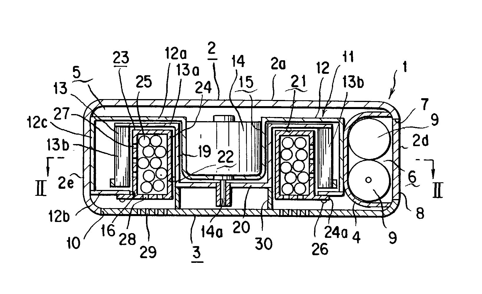
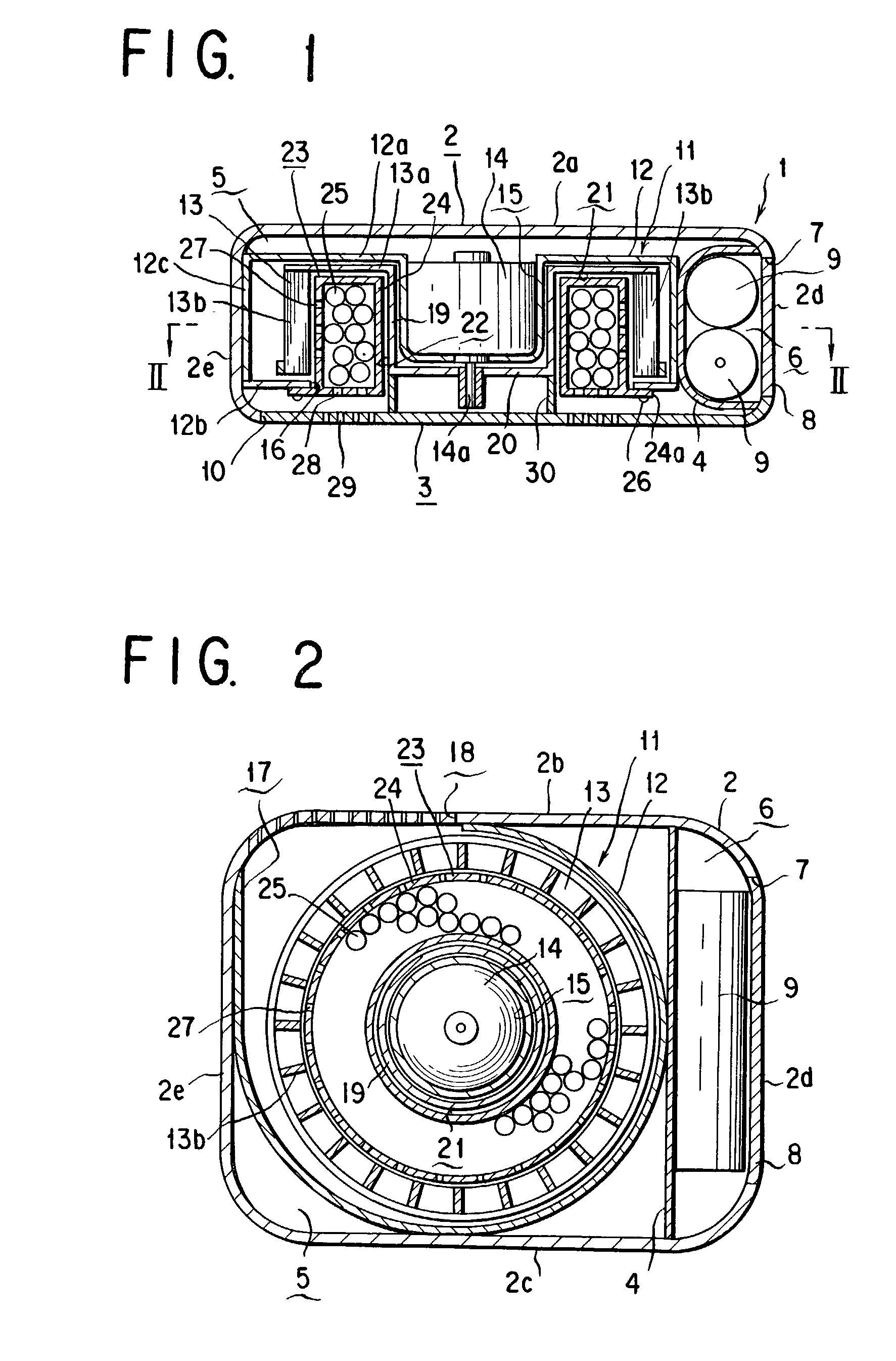
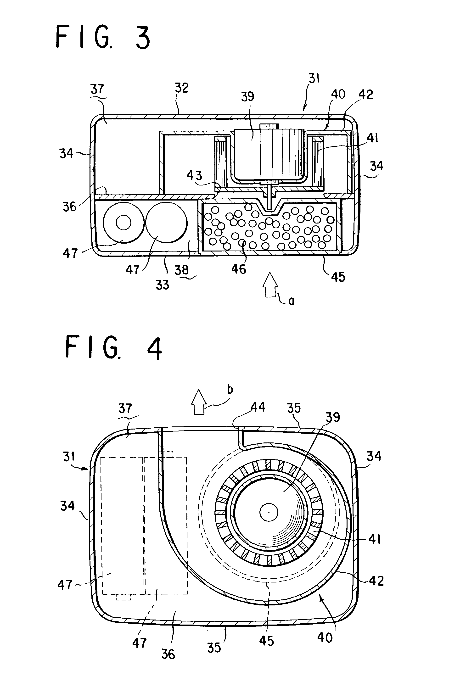
A fan type chemical diffusing apparatus includes an apparatus main body having an air inlet and an air outlet, a fan type blower disposed in the apparatus main body, and an active ingredient impregnated body or mass for containing an active ingredient. The fan type blower includes a fan casing, a motor, and a fan including a rotary disk and a plurality of blades fastened to a peripheral portion of the rotary disk and provided with a hollow space that is on an interior of the fan with respect to the blades. The fan type blower is operable to send air from the air inlet through the hollow space and out through the air outlet.

Description

TECHNICAL FIELD[0001]The present invention relates to a fan type chemical diffusing apparatus of volatilizing a chemical, a technique for diffusing an active ingredient of a volatile chemical such as an insecticide, insect repellent or moth-proofing agent, aromatic chemical and deodorant by ventilating a carrier body impregnated with the active ingredient while utilizing a fan type blower powered by a motor.[0002]More specifically, the invention relates to a fan type debugging apparatus for repelling and exterminating or excluding noxious or harmful insects including bugs such as mosquitoes, flies, cockroaches, mites, ants and centipedes and clothing bags such as skin beetles and clothes moths by ventilating a carrier body impregnated with an active ingredient while using a fan type blower powered by a motor energized by a battery or cells.BACKGROUND ART[0003]A fan type chemical volatilizing and diffusing apparatus has been known which is designed to diffuse into the atmosphere, e.g...

Claims


Application Information

Patent Timeline
Patent Type & Authority Patents(United States)
IPC IPC(8): B01F3/04A01M1/20A61L9/04A61L9/12
CPCA01M1/2033A01M1/2055A61L9/122A01N25/18A61L9/042A01N25/00
Inventor YAMASAKI, SATOSHIYAMAMOTO, KAZUNORIMATSUDA, ATSUSHI
Owner FUMAKILLA LTD
Learn More