Implant and process for producing it

a technology of implants and proxies, applied in the field of implants, can solve the problems of inability to use prostheses of this nature, and affecting the use of prostheses exposed foreign surfaces

Inactive Publication Date: 2007-02-13
JOTEC
View PDF17 Cites 69 Cited by
  • Summary
  • Abstract
  • Description
  • Claims
  • Application Information

AI Technical Summary

Benefits of technology

[0025]When the implant according to the invention is seeded with cells, these cells can rapidly migrate along the protein fibers into the matrix since the pore structure and pore size can be adjusted specifically for the given cell type.
[0053]The formation of a desired pore structure can readily be calculated and achieved using simple means, such that the elaborate construction of master plates, for example, is dispensed with, with this having the advantage of a considerable saving in time and cost.

Problems solved by technology

If use is made of synthetic materials which are one-sidedly collagen-coated on the outside, there is a great danger, for example in the case of small-lumen vascular grafts, that the exposed foreign surface of the internal lumen will induce blood coagulation and that the implanted vessel will very rapidly become occluded.
Consequently, prostheses of this nature cannot be used in the small-lumen vessel range (φ<6 mm) since, in this range, there is a danger of the vessel rapidly becoming occluded.
A particular disadvantage of these developments is the fact that the implants cannot be produced such that they are adapted to the patient but, instead, are predetermined by the donor animal with regard to the length and size of the vessel.
Furthermore, the risks of a disease being transferred by viruses or prions by way of such tissues are not completely resolved.
Another disadvantage is that it is not possible to embed an additional supporting structure into an implant which has been produced in this way in order to increase its stability.
In addition, acellularized structures are only relatively storable.
Disadvantages of these implants are the impairment of cell growth during resorption, e.g. as the result of a shift in pH when the polylactide is degraded, and the difficulty in controlling the formation of new tissue, since premature resorption can lead to the implant failing.
This method suffers from the disadvantage that the production of the membrane having a three-dimensional structure is very elaborate.
A disadvantage of this method is the fact that it is not possible to adapt the outer structure to the particular requirements of the environment into which it is to be implanted.
In addition, elaborate steps are involved in the production of the outer layer in this method since, after a freeze-drying process, the outer structure has first of all to be cut back to the desired layer thickness, something which leads to a substantial consumption of material.

Method used

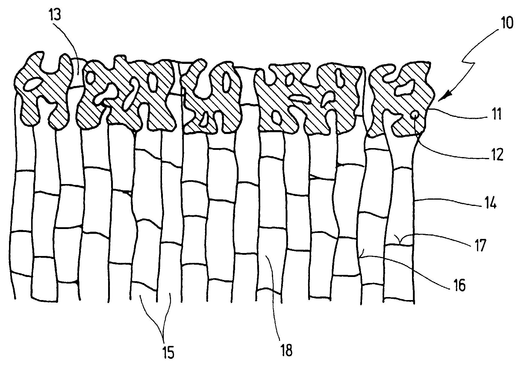
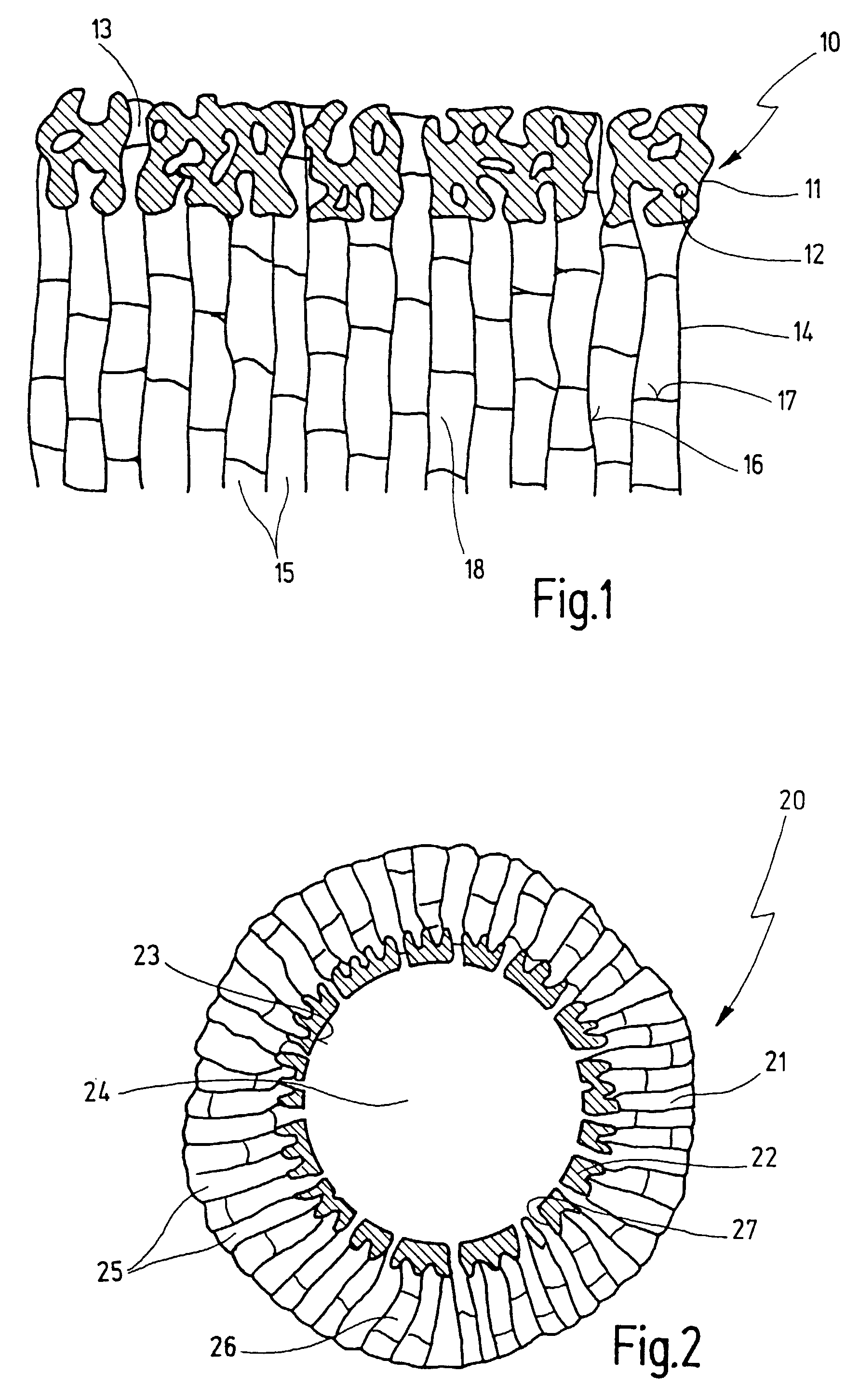
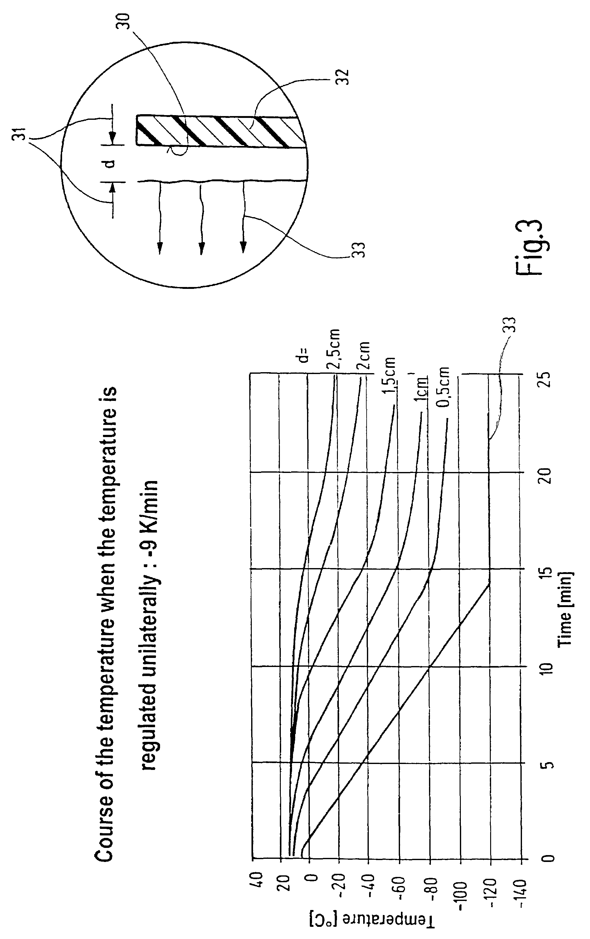

Image

  • Implant and process for producing it
  • Implant and process for producing it
  • Implant and process for producing it

Examples


example

Producing a Vascular Graft According to the Invention

[0074]Known methods are used to produce a tubular foreign structure 40 which is composed of expanded polytetrafluoroethylene (ePTFE) having an internal diameter of 4 mm and a wall thickness of 100 μm. A very high porosity is achieved as a result of stretching, such that the mean pore size, determined by the distance between the PTFE nodes, is 60 μm.

[0075]The ends of the tube, whose total length is 340 mm, are in each case pushed, by 15 mm, onto concentrically double-lumened metal tubes 41, 42 having an external diameter of 4.1 mm. At a distance of 15 mm from its end 46, the metal tube 42 possesses a flange 44. A ring 43, which can be clamped on the tube using a socket, is located on the second tube. The ring 43 possesses a clamping device 54 with which one end of the foreign structure 40 can be clamped into the ring 43. The free ends of the metal tubes can be connected to a vacuum pump.

[0076]In parallel to this, an aqueous collage...


PUM

PropertyMeasurementUnit
sizeaaaaaaaaaa
sizeaaaaaaaaaa
thicknessaaaaaaaaaa

Abstract

The invention relates to a process for producing an implant, with the implant possessing a textured foreign structure. A porous protein matrix is at least partially anchored in the textured foreign structure, with the porous protein matrix possessing a directional pore structure.

Description

BACKGROUND OF THE INVENTION[0001]1. Field of the Invention[0002]The invention relates to an implant and to a process for producing it.[0003]2. Related Prior Art[0004]Implants, and processes for producing them, have been frequently disclosed in the prior art.[0005]Implantable structures in combination with cells are used, in particular, in the field of tissue engineering, an interdisciplinary field of research which is concerned with methods and materials for producing “artificial” tissue and organ systems. Thus, it is possible to use artificially produced implants as, for example, replacements for skin, bone, cartilage, lenses or as vascular grafts.[0006]In vascular surgery, small-lumen implants are used, in particular, when it is not possible to use a patient's own blood vessels. This is the case, for example, when a specific blood vessel length is required or when the autologous blood vessels cannot be used because of their pathophysiological properties. In this connection, use is...

Claims


Application Information

Patent Timeline
Patent Type & Authority Patents(United States)
IPC IPC(8): A61F2/02A61F2/04A61L27/00A61L27/48A61L27/56
CPCA61L27/56A61L27/48
Inventor SIMMOTEIT, ROBERTFISHER GEB. SCHOOF, HEIKE
Owner JOTEC
Why Eureka
Try Eureka