Color electronic paper display device

a display device and electronic paper technology, applied in the direction of electrographic process equipment, optics, instruments, etc., can solve the problems of low efficiency of exploiting light, too narrow directivity of display devices, and white color to become dark, so as to reduce fabrication costs, facilitate the fabrication of display devices, and high reflection factor

Active Publication Date: 2007-02-13
NEC LCD TECH CORP
View PDF3 Cites 51 Cited by
  • Summary
  • Abstract
  • Description
  • Claims
  • Application Information

AI Technical Summary

Benefits of technology

[0028]In view of the above, it is an object of the present invention to provide a color electronic paper display device which can be fabricated easily without a need for precise and fine alignment of its components and is capable of providing high light reflection factor and of achieving bright display.
[0043]With the above configuration, the color filters are formed on the TFT substrate and, therefore, simply by laminating the EPD film and facing substrate on the color filters, easy fabrication of the display device is made possible without the need for further fine alignment of the components, which can reduce costs for the fabrication. Additionally, high reflection factor of color light achieves the color electronic paper display device that can provide bright display.

Problems solved by technology

However, the disclosed reflective-type liquid crystal display has a problem in that the liquid crystal display device exhibits too narrow directivity of light, that is, due to the use of a metal electrode having a flat surface as a reflective plane, its displayed contents look bright in a limited direction determined by a direction of incident light, however, the displayed contents look dark in a direction other than the specified direction.
Additionally, the disclosed reflective-type liquid crystal display device has another problem in that, due to its use of a polarization mode of light, chromatic dispersion of light is made wide and a white color cannot look like white and that, due to its use of a polarizer, the efficiency of exploiting light is low, causing a white color to become dark; in other words, the problem is that perfect paper-white display required in electronic paper is difficult.
However, if the glass substrate 21 is to be replaced with a plastic substrate for reduction of costs, it is impossible to maintain precise positioning between the color filter made of a soft plastic which can deform and the TFT glass substrate 3 with accuracy of 5 μm or so.
(1) It is necessary that the CF plastic facing substrate 5 and the TFT glass substrate are put in precise and fine alignment. However, it is difficult to put the CF plastic facing substrate 5 made of a soft plastic resin and the TFT glass substrate 3 made of glass in precise alignment with accuracy of 5 μm or so. As a result, the thick protecting layer 6 has to be formed to reinforce the CF plastic facing substrate 5 additionally.
(2) Since the thickness of the protecting layer 6 is increase, the distance between the colored layer 25 and each of the microcapsules 13 increases and a phenomenon occurs in which all incident light from, for example, the Red colored layer cannot go out through the Red colored layer and part of the light components goes out through the Green and Blue colored layers, thus causing extreme low reflection factor of color light in comparison with reflection factor of white light.

Method used


Image

  • Color electronic paper display device
  • Color electronic paper display device
  • Color electronic paper display device

Examples


embodiment

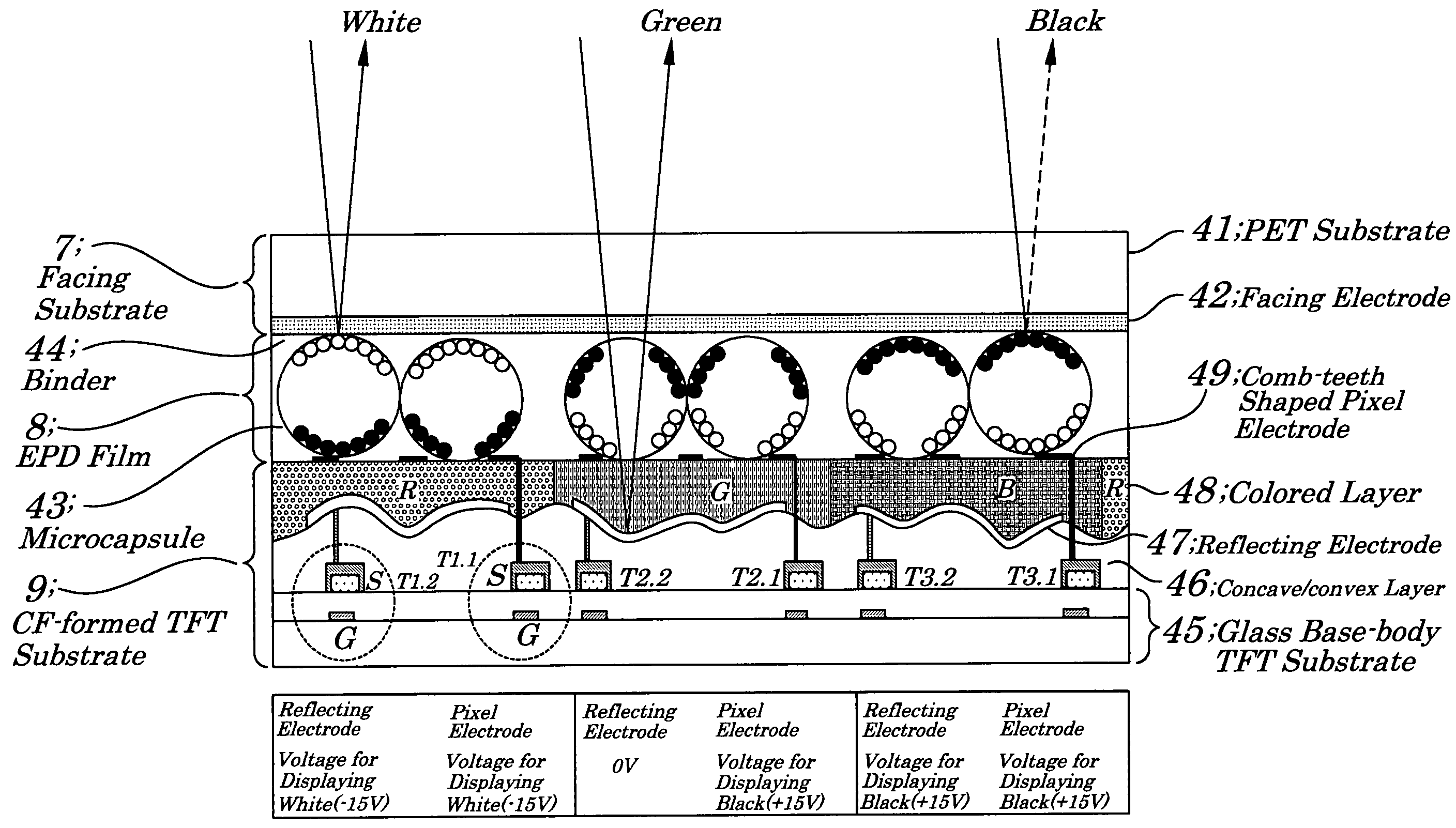
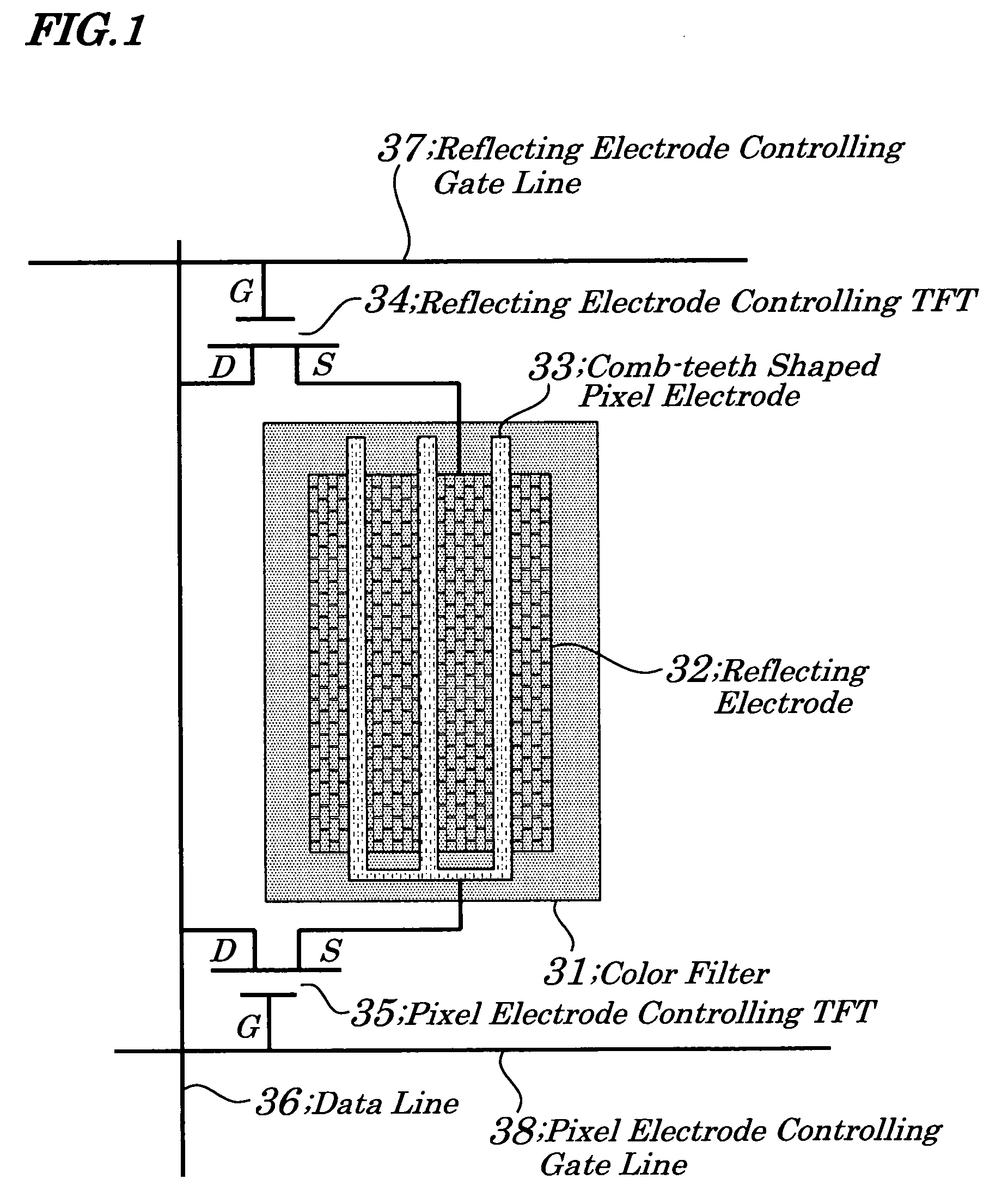
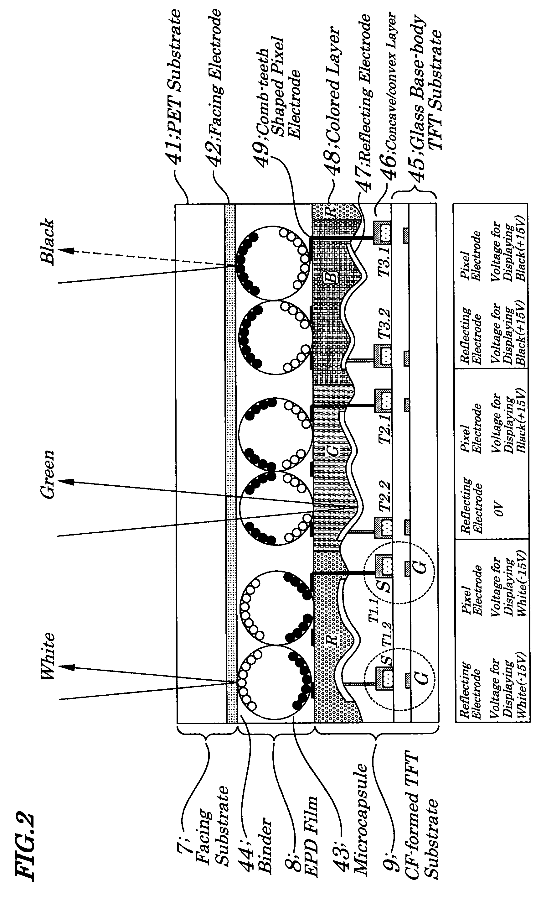
[0053]FIG. 1 is a diagram showing configurations of each pixel employed in a color electronic paper display device according to the embodiment of the present invention. FIG. 2 is a diagram showing cross-sectional configurations according to the color electronic paper display device of the embodiment. FIG. 3 is a timing chart explaining driving waveforms according to the color electronic paper display device of the embodiment.

[0054]As shown in FIG. 1, the color electronic paper display device of the embodiment chiefly includes color filters 31 each being for one color which makes up a colored layer 48, a reflecting electrodes 32, a comb-teeth shaped pixel electrodes 33, reflecting electrode controlling TFTs 34, pixel electrode controlling TFTs 35, a data line 36, a reflecting electrode controlling gate line 37, and a pixel electrode controlling gate line 38.

[0055]The color filters 31 are made up of resists each being formed so as to correspond to one color out of red (R), green (G), ...


PUM

PropertyMeasurementUnit
sizeaaaaaaaaaa
thicknessaaaaaaaaaa
widthaaaaaaaaaa

Abstract

A color electronic paper display device is provided which is easy to fabricate and can provide bright display. The color electronic paper display device includes a CF (Color Filter)-formed TFT (Thin Film Transistor) substrate in which a concave / convex layer is formed and reflecting electrode controlling TFTs and pixel electrode controlling TFTs are arranged on a glass substrate and reflecting electrodes are formed on the concave / convex layer and a colored layer made up of color filters each being for one color out of RGB (Red, Green, Blue) is formed, and each of comb-teeth shaped pixel electrodes is formed in a position corresponding to a color filter for one color, an EPD (Electrophoretic Display Device) film laminated onto an upper surface of the TFT substrate having a plurality of microcapsules making up electrophoretic elements spreading within the EPD film, and a facing substrate laminated onto an upper surface of the EPD film.

Description

BACKGROUND OF THE INVENTION[0001]1. Field of the Invention[0002]The present invention relates to a reflective-type color electronic paper display device to achieve color display by using an electrophoretic display device (EPD).[0003]The present application claims priority of Japanese Patent Application No. 2005-223514 filed on Aug. 1, 2005, which is hereby incorporated by reference.[0004]2. Description of the Related Art[0005]In recent years, research and development of an electronic paper display to be used as a display device which enables an action of “reading” without being subject to stresses, such as electronic books and electronic newspapers, is progressing. Requirements of an electronic paper display device are that it is thin, lightweight, durable (hard to crack), and easy to view (read) the same contents as printed ones. It is also required that, as the color displayed contents increases, such the electronic paper display also can display contents in colors. As the color e...

Claims


Application Information

Patent Timeline
Patent Type & Authority Patents(United States)
IPC IPC(8): G02B26/00G09G3/34G02F1/167G02F1/16756G02F1/16757G02F1/1677G02F1/1685
CPCG02F1/133514G02F1/167G02F2203/02G02F1/1685G02F1/16756G02F1/16757G02F1/1677
Inventor SAKAMOTO, MICHIAKI
Owner NEC LCD TECH CORP
Why Eureka
Try Eureka