
Constant gain digital predistortion controller for linearization of non-linear amplifiers

a non-linear amplifier and constant gain technology, applied in the field of communication systems, can solve problems such as undesirable interference, interference in adjacent channels, and distortion, and achieve the effect of improving the stability of the predistortion entity and constant gain

Inactive Publication Date: 2007-02-13
MAXLINEAR ASIA SINGAPORE PTE LTD
View PDF84 Cites 14 Cited by
  • Summary
  • Abstract
  • Description
  • Claims
  • Application Information

AI Technical Summary

Benefits of technology

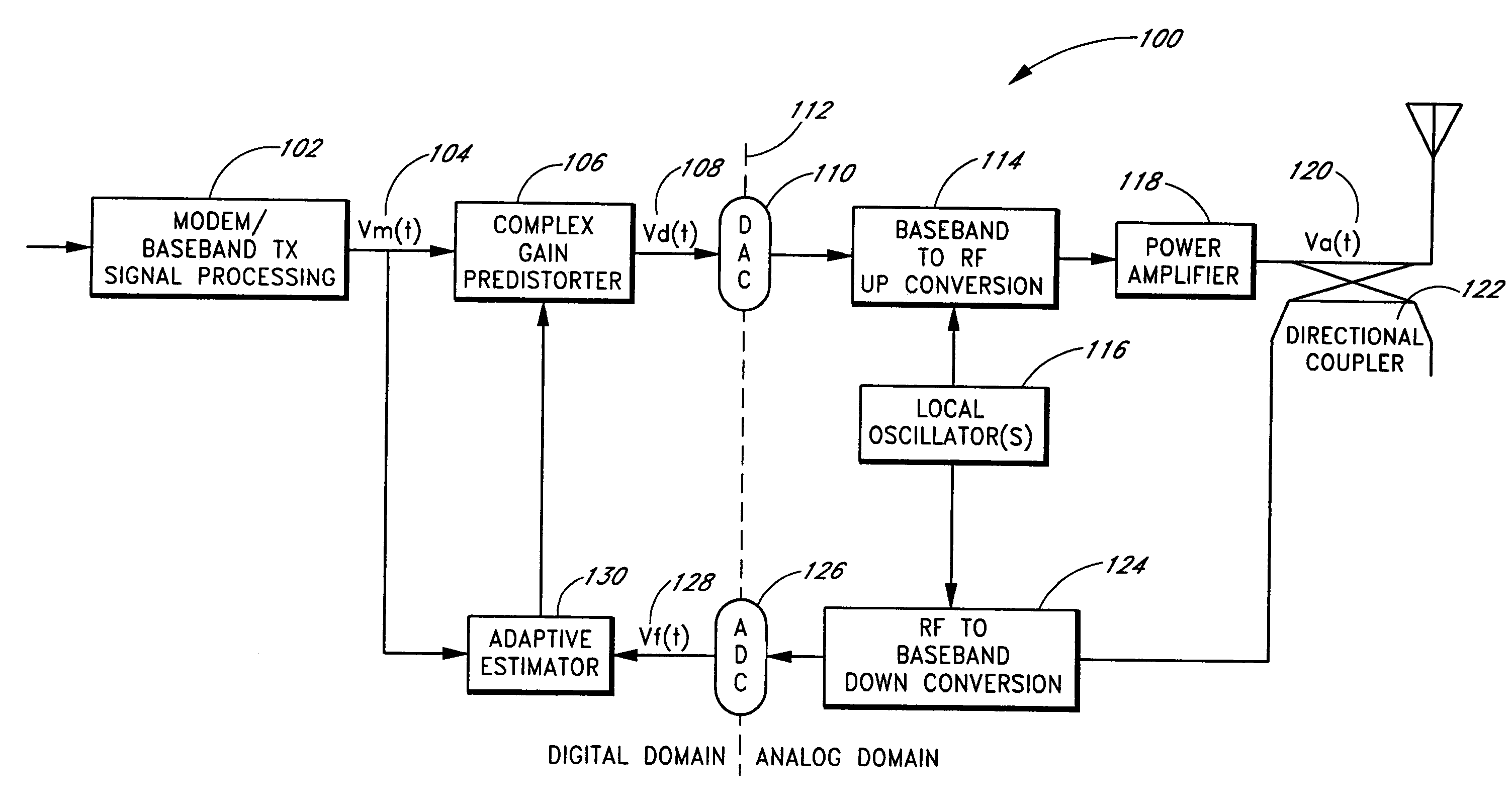
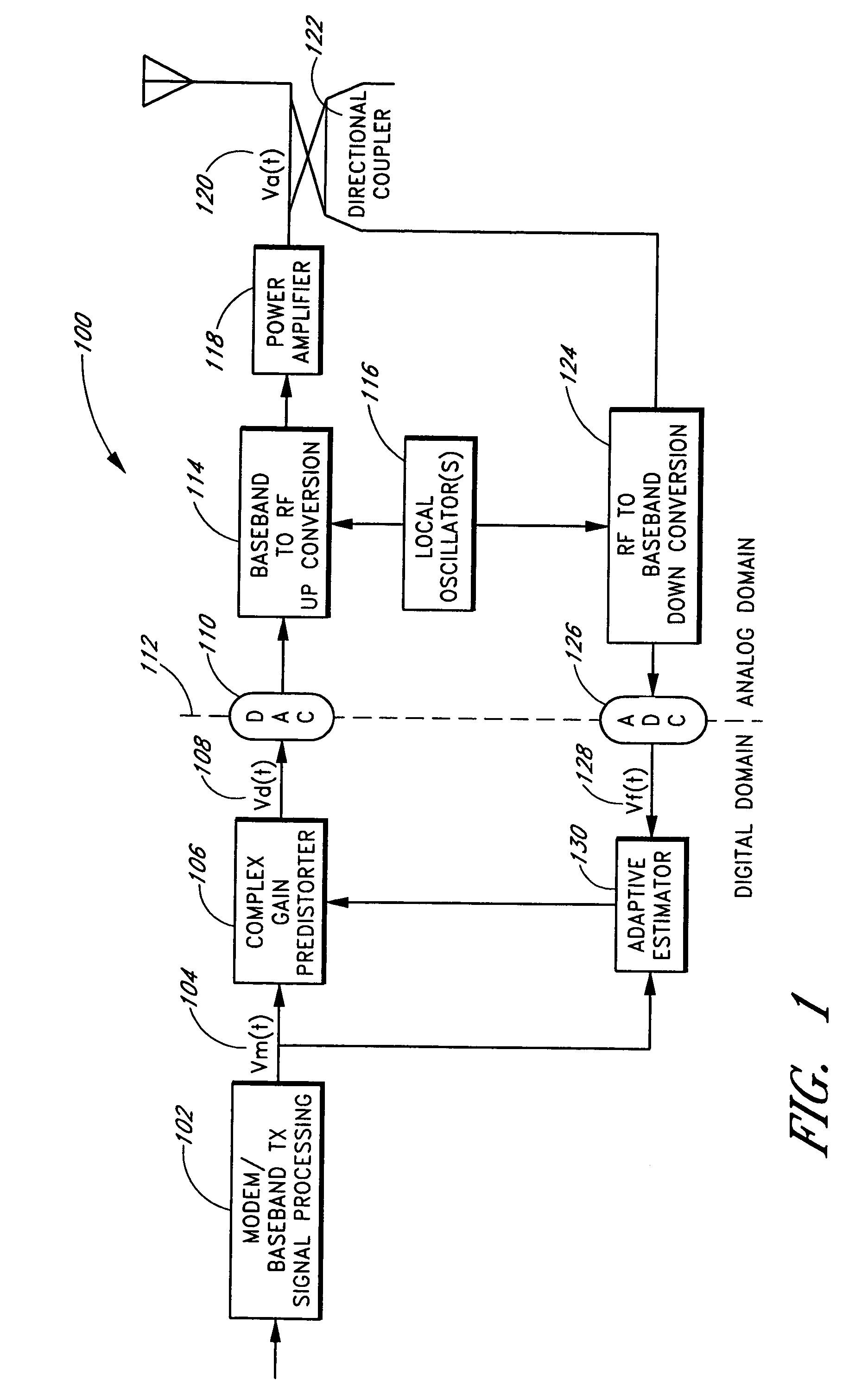
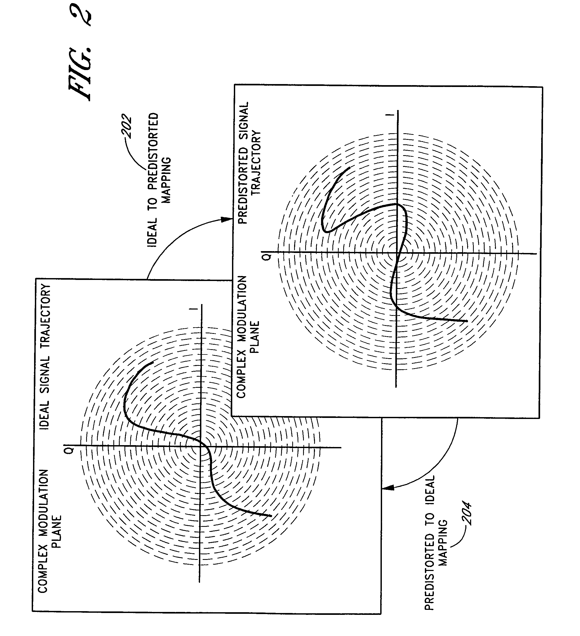
[0015]The invention is related to methods and apparatus for controlling and adapting a digital predistortion linearizer for amplification of bandlimited signals using non-linear amplifiers, such as RF power amplifiers. These non-linear amplifiers can form part of a cellular base station. A control method advantageously permits the predistortion function applied by a predistortion entity to provide a relatively constant gain. The relatively constant gain can advantageously improve the stability of the predistortion entity.
[0023]Another embodiment includes a normalizing signal pre-processor that receives a reference signal and an observed signal as inputs and generates a modified observed signal as an output. The normalizing signal pre-processor can further include: a first multiplier circuit adapted to scale the observed signal; a subtraction circuit adapted to generate an error signal from a difference between the modified observed signal and the reference signal; and adaptation logic adapted to receive the reference signal, the observed signal, the modified signal, and the error signal as inputs, and to adaptively adjust the scaling by the first multiplier circuit to reduce the magnitude of the error signal.

Problems solved by technology

It will also suffer distortion if the phase shift introduced by the amplifier is not linear over the range of frequencies present in the signal or if the phase shift caused by the amplifier varies with the amplitude of the input signal.
The products of the inter-modulation can appear within the bandwidth of the signal causing undesirable interference.
This can cause interference in adjacent channels and violate transmitter licensing and regulatory spectral emission requirements.
Although filtering can be used to remove the unwanted out-of-band distortion, filtering is not always practical, especially when the amplifier is operates on several different frequencies.
Inter-modulation is also a problem when multiple signals are amplified in the same amplifier even if individually, they do not have amplitude variations.
Even well-designed amplifiers can introduce some distortion.
In practice, perfect linearity over a wide range of amplitude is difficult to realize.
In addition, as any amplifier nears its maximum output power capacity, the output no longer increases as the input increases.
A “Class A” amplifier operating in this mode may be linear enough to transmit a signal relatively cleanly, but might typically be only about 1% efficient.
This wastes power and means that the amplifier has to be large and relatively expensive.
It also means that the waste power is dissipated as heat, which has to be removed by relatively bulky and expensive cooling systems.
However, relatively high-power linear amplifiers are generally inefficient and undesirable in a system where cost and heat dissipation are prohibitive factors, e.g., a cellular telephone base station.
Experimental analog feedback techniques are disadvantageously limited to relatively narrow operating bandwidths, are extremely sensitive to amplifier variations, and are prone to instability.
Consequently, these amplifier configurations are not appropriate for mass production.

Method used


Image

  • Constant gain digital predistortion controller for linearization of non-linear amplifiers
  • Constant gain digital predistortion controller for linearization of non-linear amplifiers
  • Constant gain digital predistortion controller for linearization of non-linear amplifiers

Examples


Embodiment Construction

[0059]Although this invention will be described in terms of certain preferred embodiments, other embodiments that are apparent to those of ordinary skill in the art, including embodiments that do not provide all of the benefits and features set forth herein, are also within the scope of this invention. Accordingly, the scope of the invention is defined only by reference to the appended claims.

[0060]Embodiments of the invention include a method and an apparatus for controlling and adapting digital predistortion linearizers for amplification of bandlimited signals using non-linear amplifiers. Advantageously, a predistortion function for a predistortion entity can be controlled to provide a relatively constant gain. The disclosed techniques can be applied to virtually any digital predistorter for an amplifier intended for bandlimited, and yet relatively wideband RF signals. The disclosed techniques can further be used in connection with multiple signals and with virtually any modulatio...


PUM


Abstract

The invention is related to methods and apparatus for controlling and adapting a digital predistortion linearizer for amplification of bandlimited signals using non-linear amplifiers. The control method advantageously permits the predistortion function applied by a predistortion entity to provide a relatively constant gain. This attribute is advantageous for operation within cellular radio systems, which often employ digital power control systems. However, the disclosed techniques can also be applicable to virtually any type of digital predistortion for which an input signal or reference signal to be amplified is predistorted in a manner that is complementary to the distortion induced by a non-linear amplifier. Embodiments of the invention advantageously enhance the practicality of using digital linearization and predistortion amplification techniques. Embodiments of the invention can automatically adjust the characteristics of a predistorted signal so that a deviation from overall linearity is compensated and subsequently reduced while maintaining a nearly constant gain attribute.

Description

CROSS-REFERENCE TO RELATED APPLICATIONS[0001]This application is a divisional application of U.S. application Ser. No. 10 / 302,782, filed Nov. 21, 2002 now U.S. Pat. No. 7,058,369, which claims the benefit under 35 U.S.C. § 119(e) of U.S. Provisional Application No. 60 / 332,151, filed Nov. 21, 2001, the disclosures of which are hereby incorporated by reference in their entireties herein.[0002]This application is related to copending applications Ser. No. 11 / 392,453, Ser. No. 11 / 392,180, Ser. No. 11 / 392,460, Ser. No. 11 / 392,286, all filed on the same date as the present application, all of which are also divisional applications of U.S. application Ser. No. 10 / 302,782, filed Nov. 21, 2002.BACKGROUND OF THE INVENTION[0003]1. Field of the Invention[0004]The invention generally relates to communications systems. In particular, the invention relates to linearizing radio frequency (RF) power amplifiers.[0005]2. Description of the Related Art[0006]Radio frequency (RF) power amplifiers are wid...

Claims


Application Information

Patent Timeline
Patent Type & Authority Patents(United States)
IPC IPC(8): H04B1/04
CPCH01Q1/243H01Q3/2605H01Q3/2682H03F1/3241H03F1/3247H03F1/3294H04B1/0475H04B2001/0441H03F2200/468H03F2201/3233H04B2001/0425H04B2001/0433H03F2200/447H03F1/3223H03F1/34H03F3/24
Inventor WRIGHT, ANDREW S.HO, DEREK J. W.KLIJSEN, BARTHOLOMEUS T. W.
Owner MAXLINEAR ASIA SINGAPORE PTE LTD
Learn More