Vacuum cleaner

a vacuum cleaner and vacuum technology, applied in the field of vacuum cleaners, can solve the problems of not providing much of the pressure drop and achieve the effects of high particle removal, and substantial resistance to the flow

Inactive Publication Date: 2007-02-20
POLAR LIGHT
View PDF133 Cites 62 Cited by
  • Summary
  • Abstract
  • Description
  • Claims
  • Application Information

AI Technical Summary

Benefits of technology

[0014]In order to achieve high levels of particle removal, cyclonic vacuum cleaners which are currently on the market incorporate a HEPA™ filter. Such filters are effective in removing small particulate matter from the air stream so that the air which exits the vacuum cleaner is essentially for refiltered. One disadvantage of such HEPA™ filters is that they provide substantial resistance to the flow of air there through. By removing the HEPA™ filter, the pressure drop which occurs during the passage of the air through the filter assembly of a vacuum cleaner may be reduced by, eg., up to 20%. Accordingly, by removing the HEPA™ filter, the flow rate through the vacuum cleaner may be substantially increased and / or the size of the motor may be reduced by eg., up to 20%. However, the amount of particulate matter which will be contained in the dirty air stream will be increased.
[0015]The instant invention provides an alternate approach to the use of such HEPA™ filters. Electrostatic filters generally provide minimal resistance to the flow of air and accordingly do not generally provide much of the pressure drop as an air stream passes there through. The electrostatic filter may be designed to remove the same size particles as are removed by the HEPA™ filter which is currently in use. Alternately, the electrostatic filter may be designed to remove even larger particles. Accordingly, by using an electrostatic filter, the pressure drops for a vacuum cleaner may be substantially reduced (compared to a vacuum cleaner using a HEPA™ filter). Further, the electrostatic filter may provide enhanced particle remover compared to even a HEPA™ filter and accordingly the clean air outlet from the vacuum cleaner may produce air which is even cleaner than that which is achieved from commercially available cyclonic vacuum cleaners which even incorporate at HEPA™ filter.
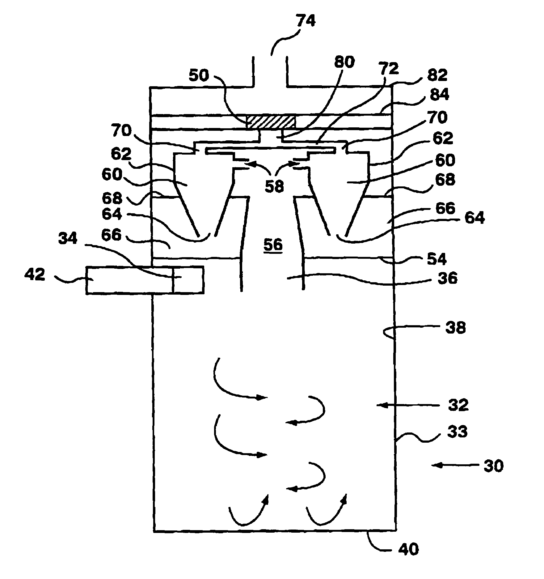
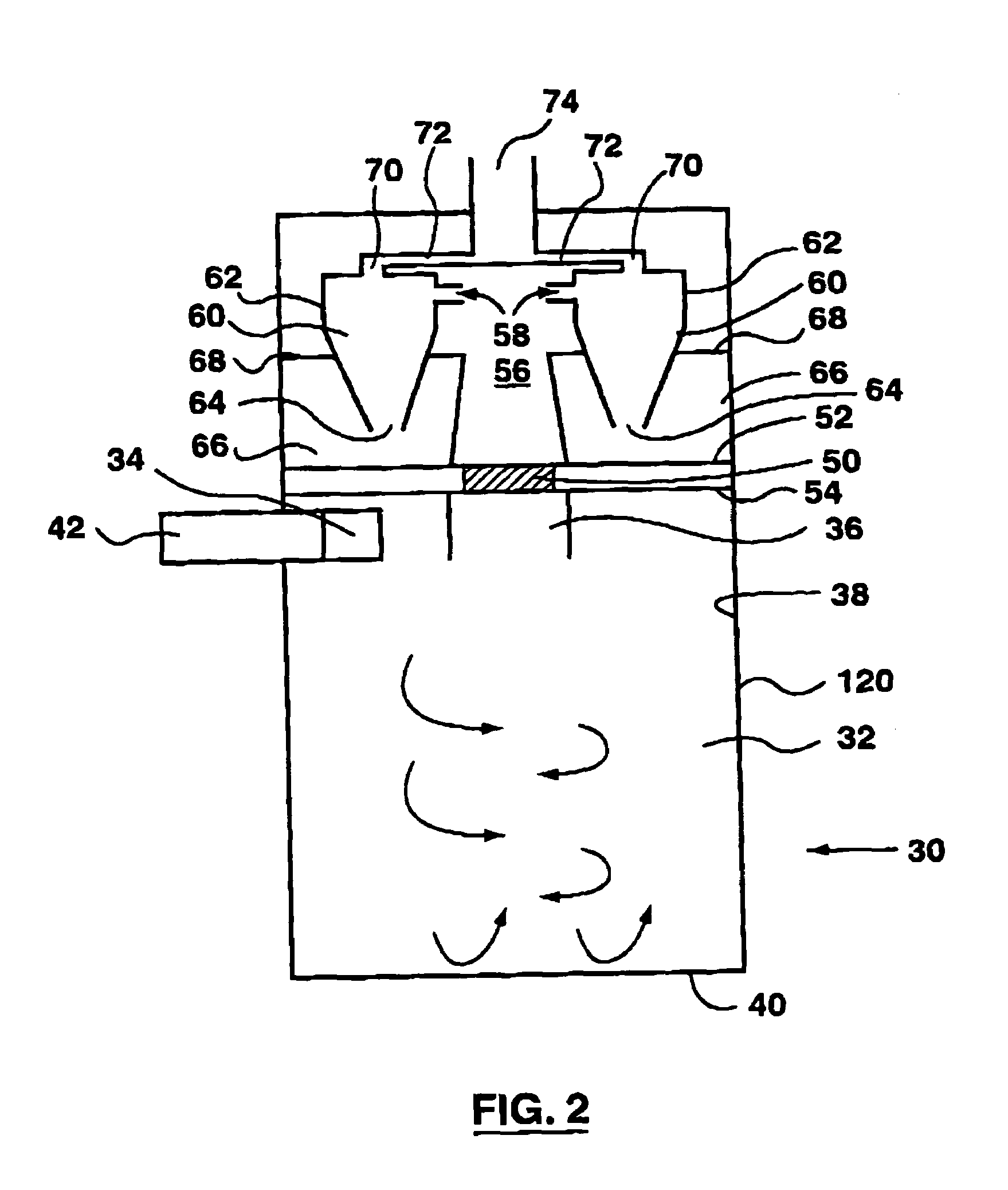
[0054]As will be appreciated, the electrostatic filter may comprise the portion of the filter assembly of the vacuum cleaner to remove the smaller particles from the dirty air stream. For example, in a vacuum cleaner having first and second cyclonic separation stages, the first cyclonic separation stage is preferably configured to remove the coarsest particles from the air stream and the second cyclonic separation staged is preferably configured to remove the smallest particles from the air stream while the electrostatic filter is designed to remove particles having an intermediate size. Thus, if the second cyclonic separation stage is positioned after the electrostatic filter, then the second cyclonic separation stage may be configured to remove the particles which are not filtered by either the first cyclonic separation stage or the electrostatic filter. As the second cyclonic separation stage need not be designed to remove the finest particulate matter, it may be of a lower efficiency then would otherwise by useable and accordingly may have a larger diameter. By increasing the diameter of second stage cyclones, the pressure drop across each second stage cyclone will be reduced thereby producing a further reduction in the pressure drop which occurs by the passage of air through the filter assembly of the vacuum cleaner and further reducing the power (size of motor) which is required.

Problems solved by technology

One disadvantage of such HEPA™ filters is that they provide substantial resistance to the flow of air there through.
Electrostatic filters generally provide minimal resistance to the flow of air and accordingly do not generally provide much of the pressure drop as an air stream passes there through.

Method used


Image

  • Vacuum cleaner
  • Vacuum cleaner
  • Vacuum cleaner

Examples


Embodiment Construction

[0071]The filter assembly of the instant invention may be used in conjunction with any vacuum cleaner. For example, the filter assembly may be used for an upright vacuum cleaner, a canister vacuum cleaner or a central vacuum cleaner or the like. The dirty air stream which is processed using the filter assembly described herein may be collected by, for example, a wand or rotating brush positioned in the head of a vacuum cleaner as is known in the art. Such dirty air streams typically comprise dirt of varying particle sizes entrained in an air stream. It will be appreciated that the invention may also be used with a wet / dry vacuum cleaner.

[0072]The filter assembly may be used in conjunction with any design known in the art. For example, as shown in FIGS. 2 and 3, the cyclone may be a cylindrical cyclone having a dirty air feed conduit which is positioned exterior to cyclone bin 120. Alternately, as shown in FIGS. 4 and 5, the cyclone may be a cylindrical cyclone having a dirty air fee...


PUM

PropertyMeasurementUnit
pressureaaaaaaaaaa
densityaaaaaaaaaa
sizeaaaaaaaaaa

Abstract

A method for filtering a dirty air stream in a vacuum cleaner to obtain a clean air stream comprises subjecting the dirty air stream to a first cyclonic separation stage to obtain a partially cleaned air stream and subjecting the partially cleaned air stream to an electronic filtration stage and optionally a second cyclonic separation stage to obtain the clean air stream. The electronic filtration stage is optionally removable with a cyclonic cleaning stage from the vacuum cleaner. The electronic filtration stage is optionally an electrostatic precipitator which utilizes air flow through the vacuum cleaner to generate the voltage used by the electrostatic precipitator.

Description

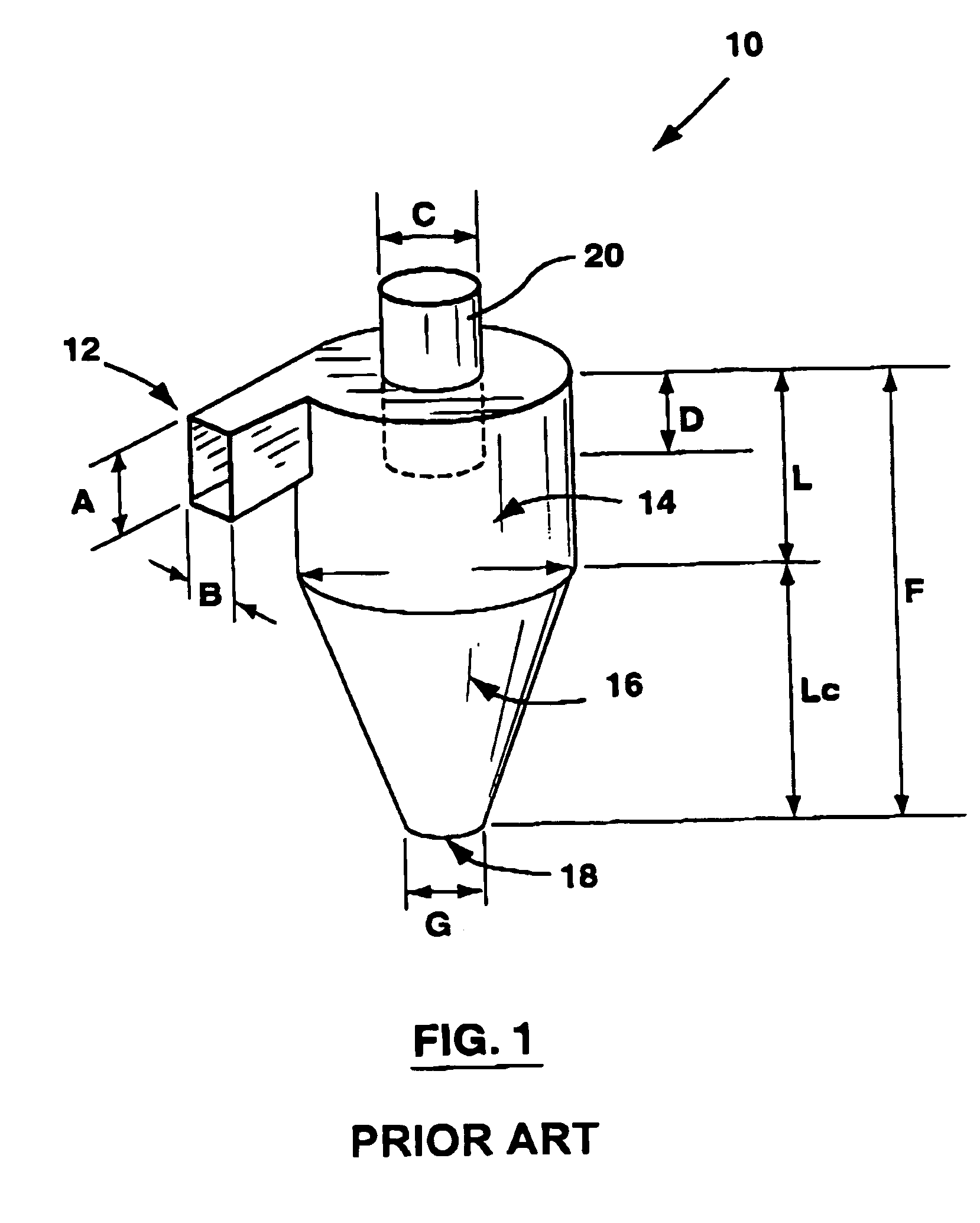
[0001]This applicatin is a continuation of U.S. application Ser. No. 10 / 043,337, now allowed, which is a continuation of U.S. patent application Ser. No. 09 / 478,891 filed on Jan. 7, 2000 which has issued as U.S. Pat. No. 6,383,266 which is a continuation-in-part of U.S. patent application Ser. No. 09 / 227,712 filed on Jan. 8, 1999 which has issued as U.S. Pat. No. 6,238,451.FIELD OF THE INVENTION[0002]This invention relates to vacuum cleaners which have a cyclonic separation apparatus. In another aspect, the invention relates to an electrostatic precipitator.BACKGROUND OF THE INVENTION[0003]Cyclone separators, which are sometimes referred to merely as cyclones, are devices that utilize centrifugal forces and low pressure caused by spinning motion to separate materials of differing density, size and shape. FIG. 1 illustrates the operating principles in a typical cyclone separator (designated by reference numeral 10 in FIG. 1). The following is a description of the operating principles...

Claims


Application Information

Patent Timeline
Patent Type & Authority Patents(United States)
IPC IPC(8): B01D45/12A47L9/12A47L9/16B01D45/16B01D50/00B04C5/24
CPCA47L9/122A47L9/1625A47L9/1641A47L9/1666B01D45/16B01D50/00B04C5/24A47L9/1691Y10S55/03B04C2009/002
Inventor CONRAD, WAYNE ERNESTCONRAD, HELMUT GERHARD
Owner POLAR LIGHT
Why Eureka
Try Eureka