LDI/MALDI source for enhanced spatial resolution

a spatial resolution and ldi technology, applied in the field of mass spectrometry, can solve the problems of difficult or impossible to focus the beam to the desired size, too large for tissue imaging applications, and the difficulty of placing a short focal length lens, etc., to achieve a small beam spot and higher resolution

Inactive Publication Date: 2007-02-20
THERMO FINNIGAN
View PDF15 Cites 37 Cited by
  • Summary
  • Abstract
  • Description
  • Claims
  • Application Information

AI Technical Summary

Benefits of technology

[0010]By positioning the beam-focusing optics and / or the imaging optics on a different side of the sample support from the ion optical device, the design of the LDI / MALDI source is less constrained by the limited space around the sample, thereby permitting use of a short focal length beam-focusing lens that must be positioned at close proximity to the sample. Use of a short focal length lens produces a smaller beam spot than would be possible using prior art LDI / MALDI system architectures, which in turn allows for acquisition of mass spectral images at higher resolutions.

Problems solved by technology

In most commercially available MALDI sources, the spot size has a diameter of around 100 μm, which is too large for some tissue imaging applications.
However, the presence and positioning in the ionization source chamber of the ion guide or other optics, which transport the ions from the sample location to the mass analyzer, will often interfere with the placement of a short focal length lens, thereby making it difficult or impossible to focus the beam to the desired size.
The placement of a short focal length lens may also be rendered more difficult by the presence of discrete viewing optics employed to acquire an image of the sample.

Method used


Image

  • LDI/MALDI source for enhanced spatial resolution
  • LDI/MALDI source for enhanced spatial resolution
  • LDI/MALDI source for enhanced spatial resolution

Examples


Embodiment Construction

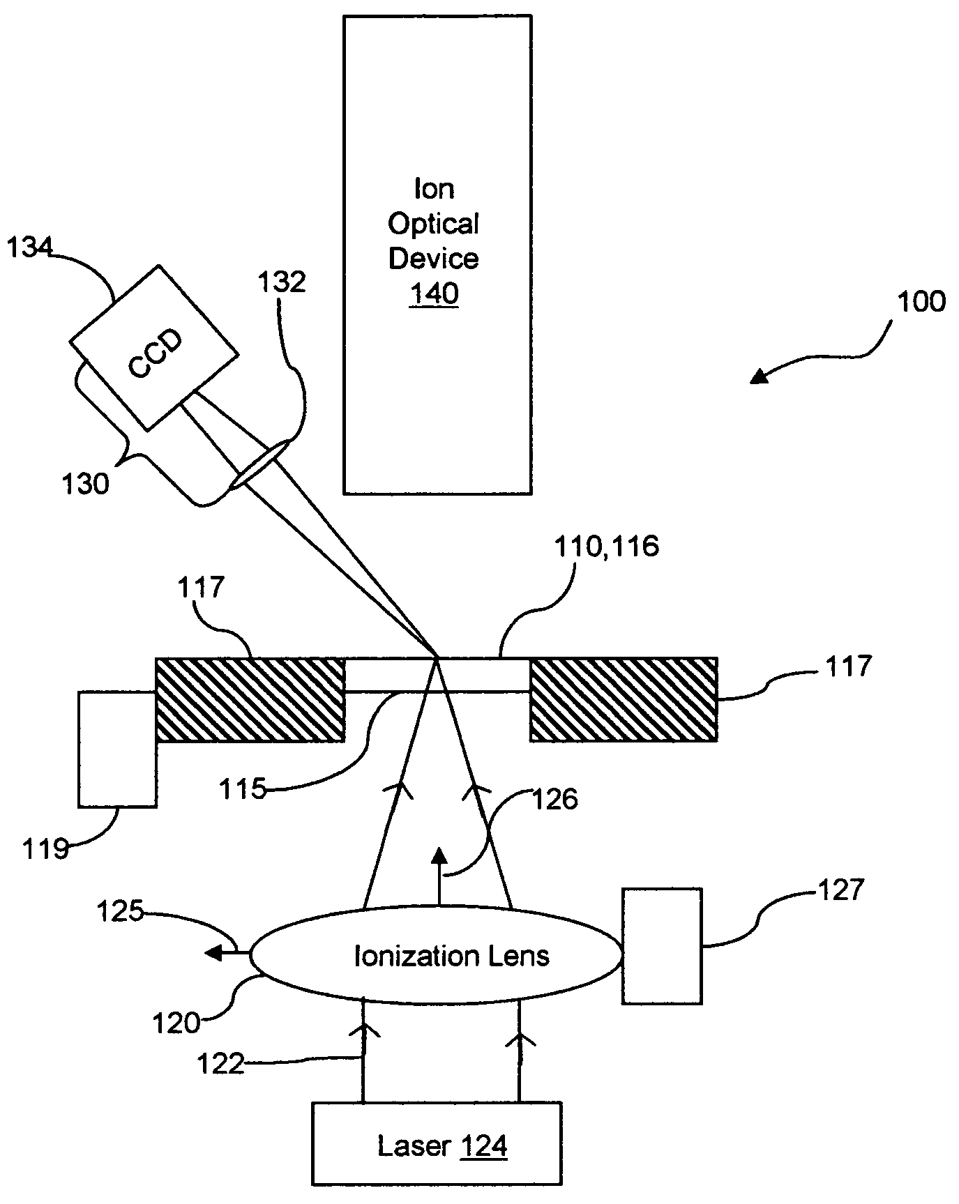
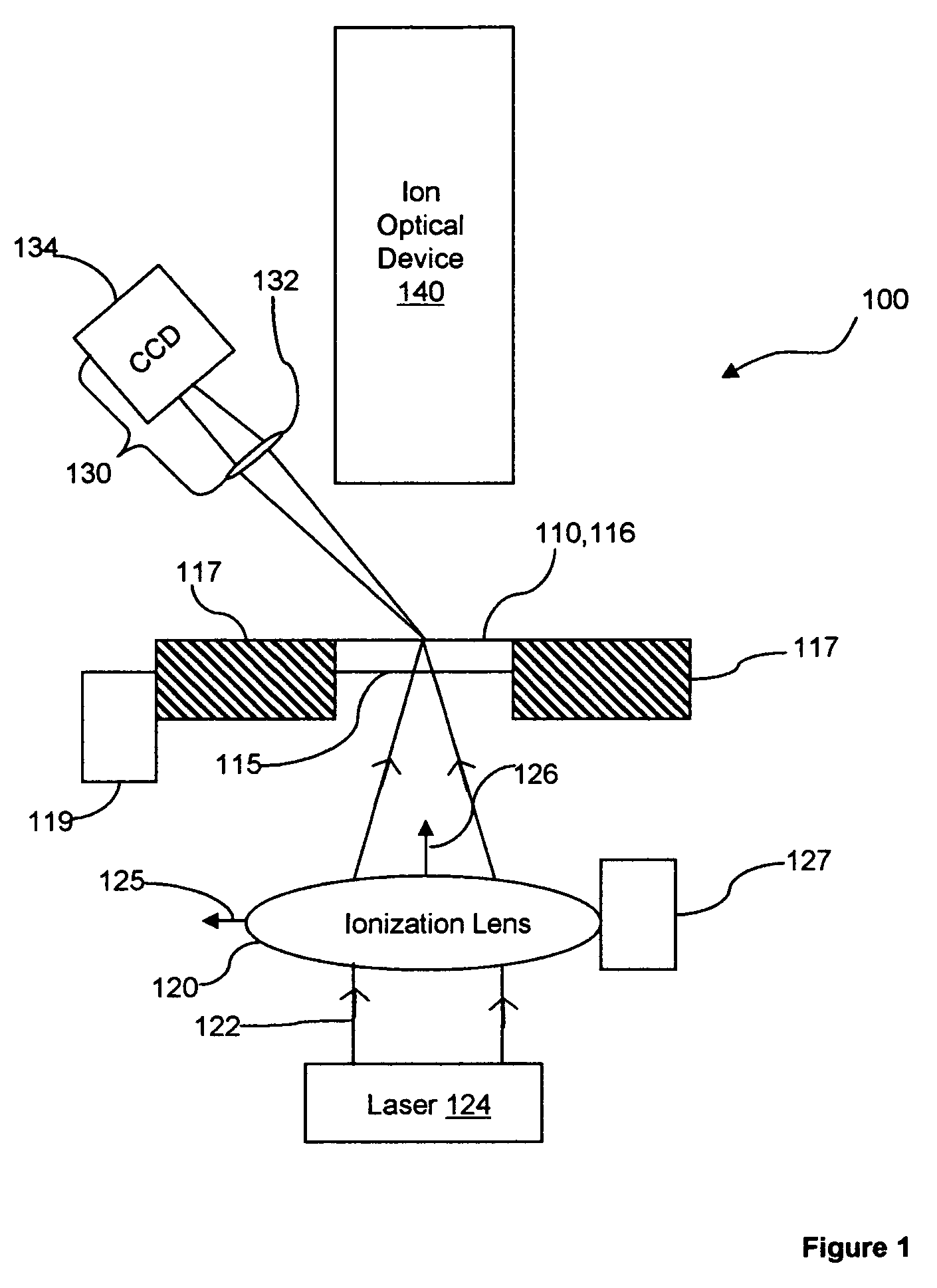
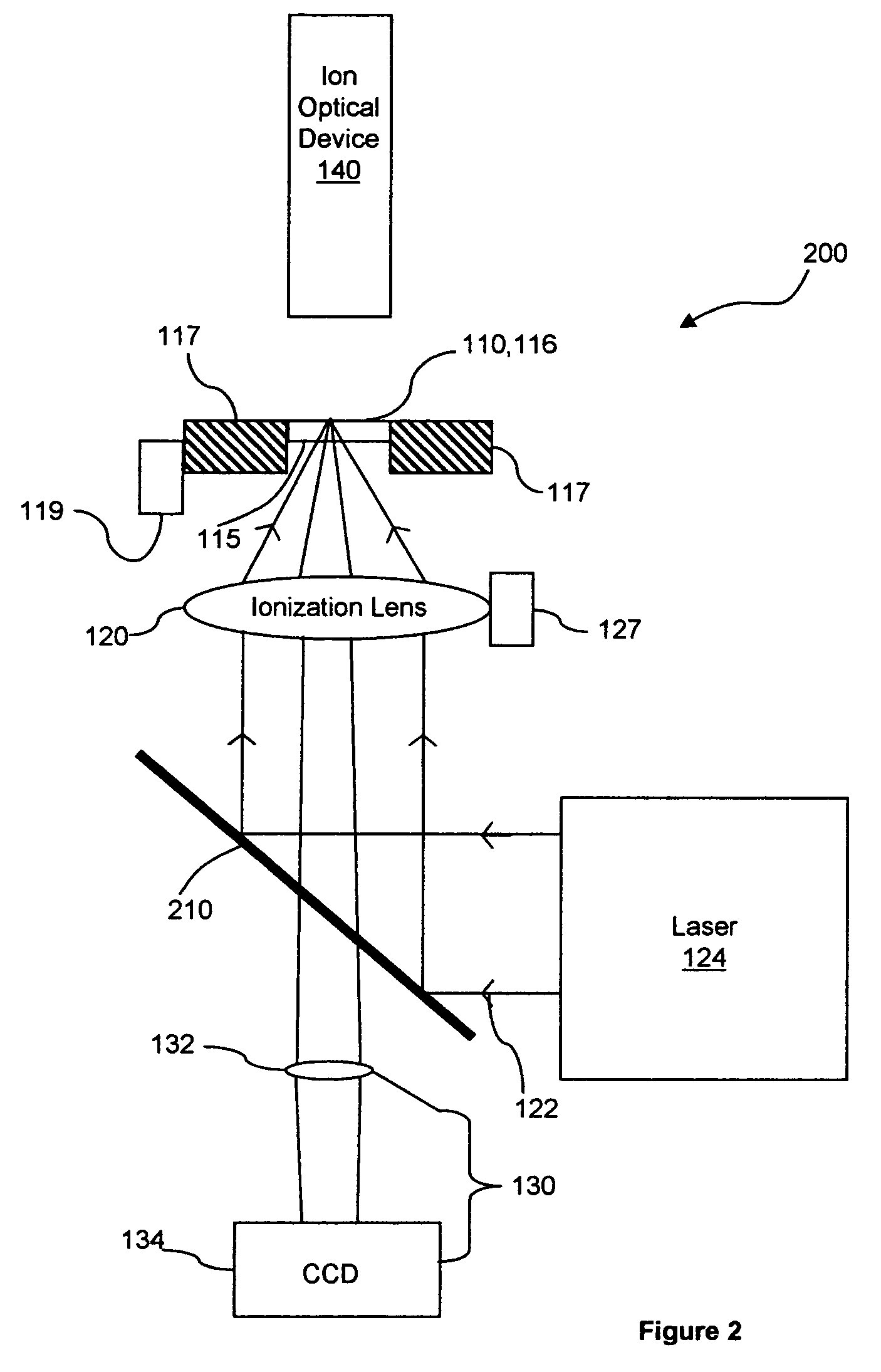
[0016]In one aspect of the invention, a laser desorption / ionization source or matrix-assisted laser desorption / ionization source (referred to collectively as an LDI / MALDI source) is provided which accommodates a sample support configured to support one or more sample(s) on a front surface thereof. The sample support is at least locally transparent at the wavelength of the irradiation beam. Transparency may be provided by the modification of a non-transparent sample support with transparent windows or openings that underlie the sample(s); alternatively, the entire sample support may be constructed from a transparent material such as quartz. Beam focusing optics and / or viewing optics may be disposed adjacent a rear surface of the sample support for, respectively, focusing a beam of radiation onto the sample and acquiring an image of the sample. An ion optical device, such as a multipole ion guide, is disposed adjacent the front surface of the sample support and functions to collect an...


PUM


Abstract

A MALDI/LDI source is disclosed that includes an ion optical device and beam-focusing optics disposed on opposite sides of a sample support that is at least locally transparent in a region underlying the sample to allow transmission of a radiation beam therethrough. A laser or other radiation source, located adjacent a rear surface of the sample support, emits a beam of radiation that is focused by the beam focusing optics and traverses the transparent region of the sample support to impinge on the sample. Ions produced by irradiation of the sample are collected by an ion optical device located adjacent the front surface of the sample support. By locating the ion optical device and beam-focusing optics on opposite sides of the sample support, short focal length beam-focusing optics may be utilized, thereby facilitating smaller beam spot sizes. This may be particularly useful for mass spectral tissue imaging and other applications where high spatial resolution analysis of a differentiated sample is desirable.

Description

BACKGROUND[0001]1. Field of the Invention[0002]The invention is in the field of mass spectrometry and more specifically in the field of ionization sources for mass spectrometry.[0003]2. Related Art[0004]Laser-based ionization techniques, which include laser desorption / ionization (LDI) and matrix-assisted laser desorption / ionization (MALDI), are useful tools for mass spectrometric analysis. These techniques involve irradiating a sample containing an analyte substance with a short pulse of radiation, typically emitted by a laser. The radiation is absorbed by the sample, resulting in the desorption and ionization of analyte molecules from the sample. In the MALDI process, the sample is prepared by associating the analyte substance with a matrix material, which is highly absorbent at the irradiation wavelength and which assists in the desorption and ionization of the analyte molecules. MALDI is a particularly useful technique for the analysis of large biological molecules, such as pepti...

Claims


Application Information

Patent Timeline
Patent Type & Authority Patents(United States)
IPC IPC(8): H01J49/04H01J27/00H01J49/26
CPCH01J49/164H01J27/24
Inventor IZGARIAN, NICOLAE
Owner THERMO FINNIGAN
Why Eureka
Try Eureka