Spray cool system with a dry access chamber

a dry access and cooling system technology, applied in domestic cooling apparatus, power cables, semiconductor/solid-state device details, etc., can solve the problems of user often coming in direct contact with coolant, loss of coolant, and inability to efficiently cool modern high-end electronics. , to achieve the effect of prolonging the life of water removing filters, reducing the amount of time required, and reducing the introduction of water

a dry access and cooling system technology, applied in domestic cooling apparatus, power cables, semiconductor/solid-state device details, etc., can solve the problems of user often coming in direct contact with coolant, loss of coolant, and inability to efficiently cool modern high-end electronics. , to achieve the effect of prolonging the life of water removing filters, reducing the amount of time required, and reducing the introduction of water

US7180741B1Active Publication Date: 2007-02-20PARKER INTANGIBLES LLC

Image

  • Spray cool system with a dry access chamber
  • Spray cool system with a dry access chamber
  • Spray cool system with a dry access chamber

Examples


Embodiment Construction

A. Overview

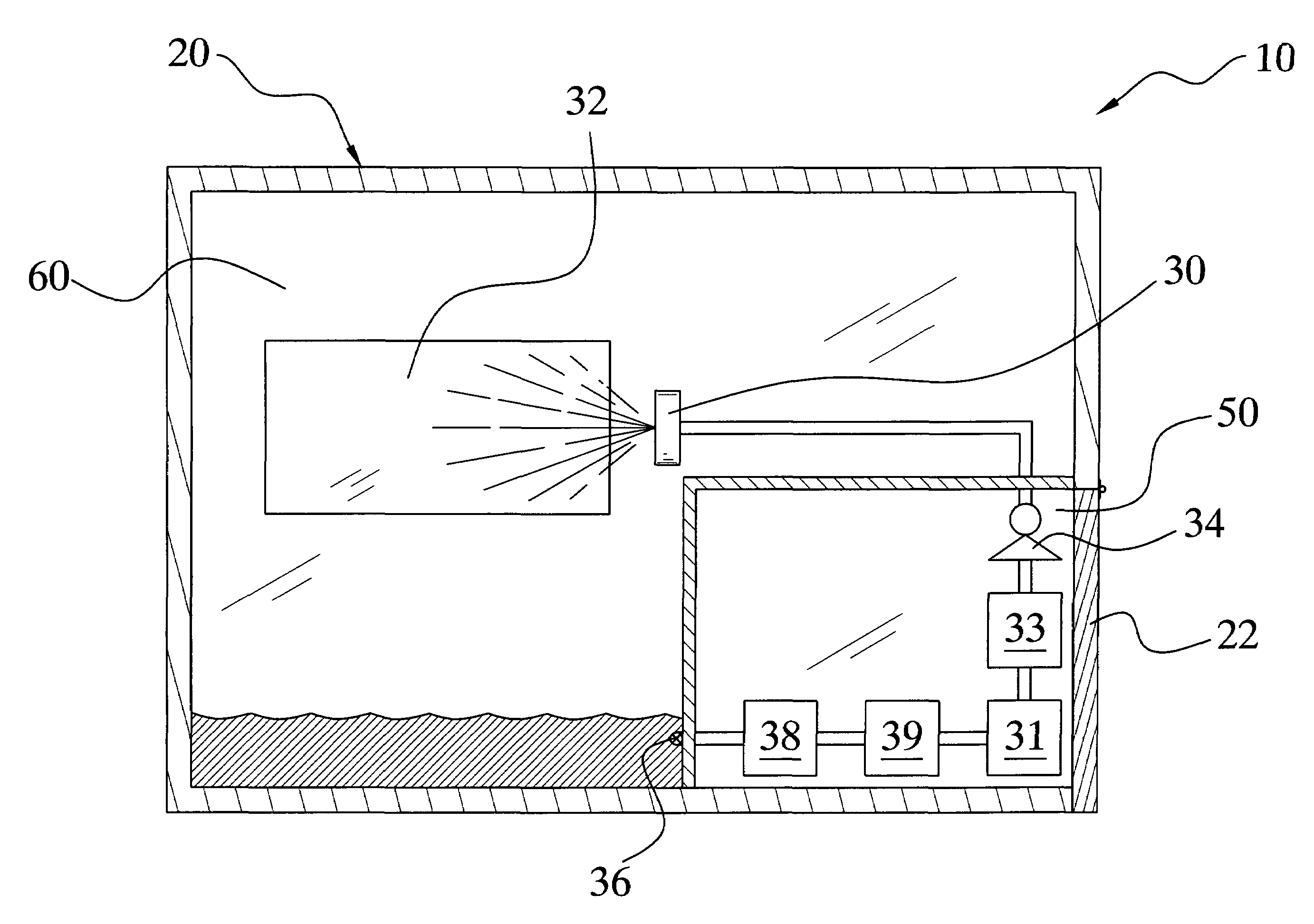
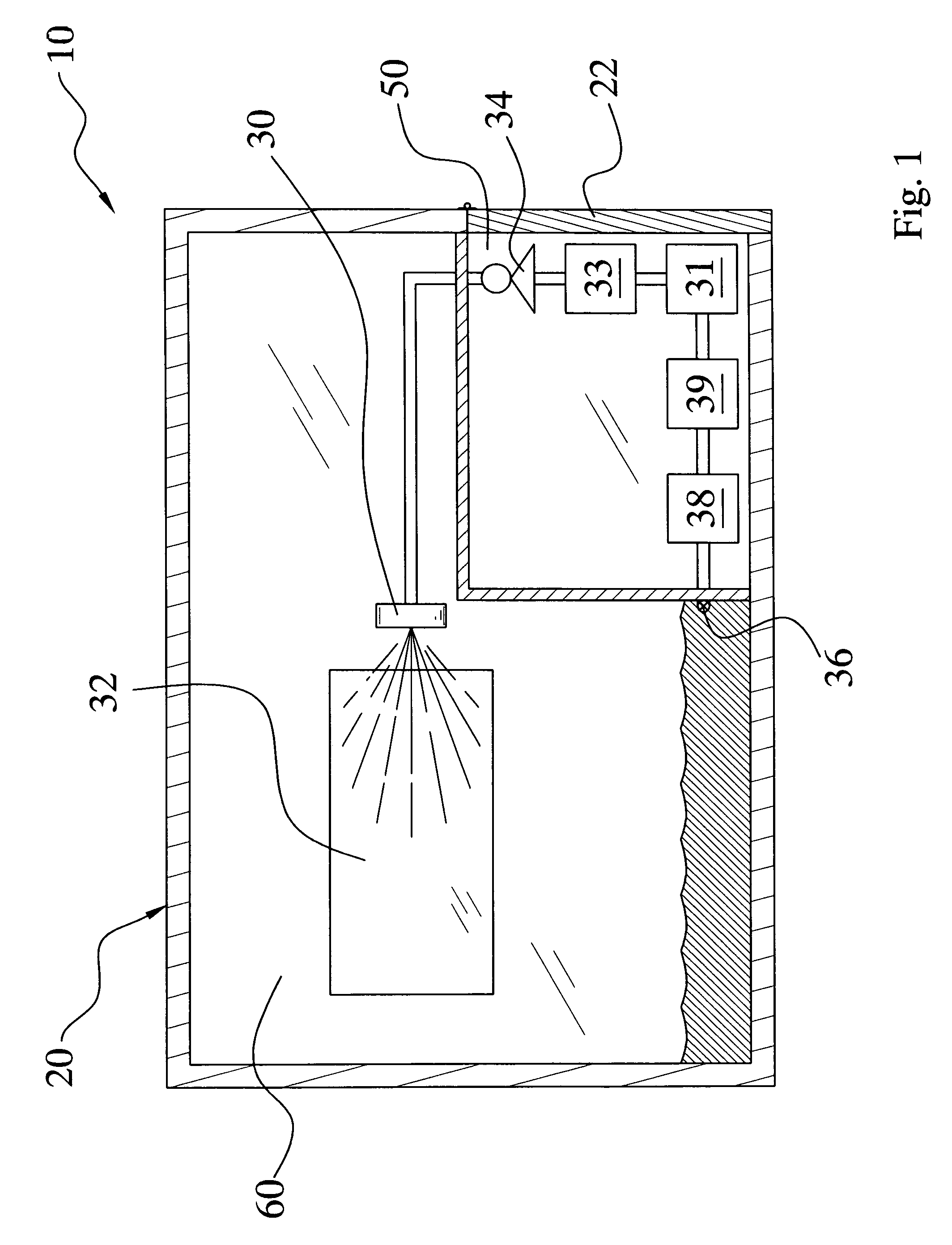
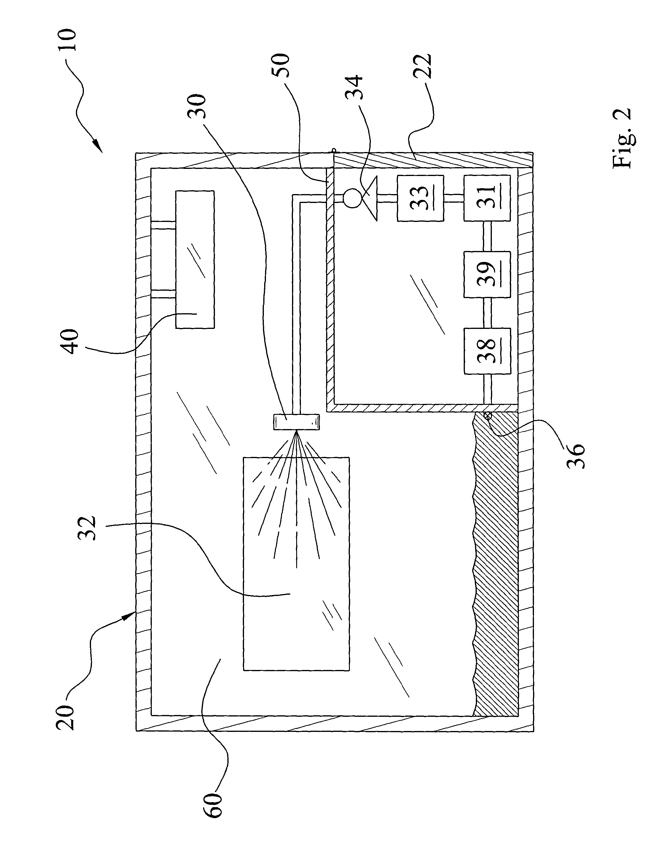
[0036]Turning now descriptively to the drawings, in which similar reference characters denote similar elements throughout the several views, FIGS. 1 through 9 illustrate a spray cool system with a dry access chamber 10, which comprises a dry access chamber includes a chassis 20 having a dry chamber 50 and a wet chamber 60. A dry access door 22 and a wet access door 24 are removably attached about the dry chamber 50 and the wet chamber 60 respectively for providing access to the same. Spray cool components such as a card cage 32 and a spray unit 30 are positioned within the wet chamber 60. Spray cool components such as but not limited to filters 39, pumps, heaters 33, sensors 31, separators 38 and the like are positioned within the dry chamber 50 for efficient dry access.

B. Chassis

[0037]The chassis 20 may have various shapes, structures and configurations. The chassis 20 illustrated in the drawings should not be interpreted to limit the scope of protection of the present i...


PUM


Abstract

A spray cool system with a dry access chamber for providing convenient access to specific spray system components in a dry chamber separate from the wet chamber. The spray cool system with a dry access chamber includes a chassis having a dry chamber and a wet chamber. A dry access door and a wet access door are removably attached about the dry chamber and the wet chamber respectively for providing access to the same. Spray cool components such as a card cage and a spray unit are positioned within the wet chamber. Spray cool components such as but not limited to filters, pumps, heaters, sensors, separators and the like are positioned within the dry chamber for efficient dry access.

Description

CROSS REFERENCE TO RELATED APPLICATIONS[0001]Not applicable to this application.STATEMENT REGARDING FEDERALLY SPONSORED RESEARCH OR DEVELOPMENT[0002]Not applicable to this application.BACKGROUND OF THE INVENTION[0003]1. Field of the Invention[0004]The present invention relates generally to spray cool thermal management systems and more specifically it relates to a spray cool system with a dry access chamber for providing convenient access to specific spray system components in a dry chamber separate from the wet chamber.[0005]2. Description of the Related Art[0006]Modern electronic devices have increased thermal management requirements. Conventional dry thermal management technology simply is not capable of efficiently cooling modern high-end electronics.[0007]Spray thermal management technology is being adopted today as the most efficient option for thermally managing electronic systems. U.S. Pat. No. 5,220,804 entitled High Heat Flux Evaporative Spray Cooling to Tilton et al. desc...

Claims


Application Information

Patent Timeline
20 Feb 2007
Publication
US7180741B1
IPC
H05K7/20; F25D17/02; F28F7/00; H01L23/34; H02G3/03
CPC
H05K7/20345
Inventors
KNIGHT, PAUL A.; FALES, BRENT M.