Frequency offset differential pulse position modulation

a pulse position and frequency offset technology, applied in the field of computer networks, can solve the problems of increasing operating and maintenance costs, reducing the palatable structure of structured wiring systems, and increasing the cost of moving an average ethernet unshielded twisted pair (“utp”) connection of such a lan, so as to increase the amount of data, reduce blanking time, and increase data rate

Inactive Publication Date: 2007-02-20
RADIOLAN
View PDF10 Cites 6 Cited by
  • Summary
  • Abstract
  • Description
  • Claims
  • Application Information

AI Technical Summary

Benefits of technology

[0013]Accordingly, the present invention provides such a need by utilizing a frequency offset differential pulse position modulation scheme to transmit data between computing devices within a wireless network system (100). The differential pulse position modulation component of the scheme enables the present invention to provide relative immunity to interference for the system (100). In particular, such immunity from interference is achieved by utilizing a blanking time between pulse positions, which is large enough to allow the interference between pulses to subside and not interfere with the quality of the data transmission. The frequency offset component of the scheme enables the system to utilize multiple frequency channels to enable the system (100) to achieve higher data rates. In particular, by utilizing a time offset between the frequency channels, between which the system switches, the blanking time can be reduced, thereby increasing the amount of data that can be transmitted within a set period of time in the system (100).

Problems solved by technology

Unfortunately, as organizations grow more dependent on these high speed LANs, structured wiring systems have become less palatable.
As a result, operating and maintenance costs are growing as users attempt to keep pace with this rapidly evolving environment.
In addition, more than 35 percent of problems with LANs using hubs and structured wiring and 70 percent of problems with LANs without hubs and structured wiring typically are attributable to the cabling of the LAN.
In particular, the costs to move an average Ethernet unshielded twisted pair (“UTP”) connection of such a LAN average approximately $500 or more (in parts and labor) per node.
This cost further increases in major metropolitan areas where increased labor costs and a prevalence of fiber-based LANs exist.
However, most of these WLAN products failed to meet several key criteria essential to wide-scale adoption.
The system failed to be fast (e.g. at least 10 Megabits per second), was not simple (e.g. plug and play) and was not economical (e.g. less than $500 per node).
These WLANs, however, exhibit one drawback or another such as being too slow, restricted to certain environments or too expensive.
Unfortunately conventional WLANs do not meet more than a few of these requirements with some failing to satisfy even one.
Unfortunately, multipath interference, or Rayleigh fading, occurs when radio waves reflect off the surface of physical objects, producing a complex pattern of interfering waves which causes signals to meet at the antenna and cancel each other out.
In addition, further interference is generated by other devices, which operate in the 2.4 GHz frequency range.
These forms of interference present a design challenge for conventional WLAN systems, which have resulted in many conventional 3G WLANs relying upon a spread spectrum scheme.
Unfortunately, by overcoming this interference with spread spectrum technology, such as Frequency Hopping Spread Spectrum (“FHSS”) and Direct Sequence Spread Spectrum (“DSSS”), these 4G WLANs are limited to data rates of up to 1 Mbps to 2 Mbps.
While FHSS and DSSS. at first, may appear to be simpler to implement than other schemes, there still are some very subtle difficulties that occur when strong interfering signals exist in such a system.
For example, the basis of the noise immunity within a DSSS-based system is the fact that the desired signal and interference (or noise) are uncorrelated.
Therefore, even though the use of spread spectrum techniques combined with more available bandwidth and more complex modulation schemes allows such WLANs to operate at higher data rates, those data rates are not as high as desired (e.g. over 10 Mbps).

Method used


Image

  • Frequency offset differential pulse position modulation
  • Frequency offset differential pulse position modulation
  • Frequency offset differential pulse position modulation

Examples


Embodiment Construction

[0028]Embodiments of the present invention are now described with reference to the Figures where like reference numbers indicate identical or functionally similar elements and the left most digit(s) of each reference number corresponds to the Figure in which the reference number is first used.

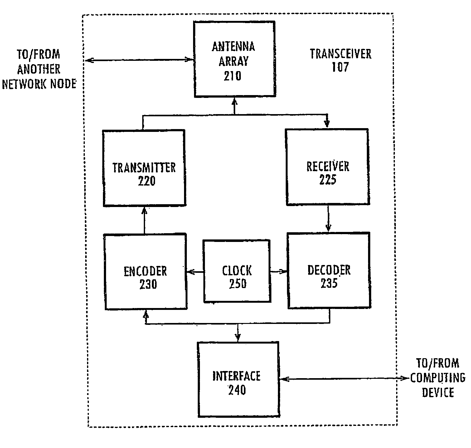
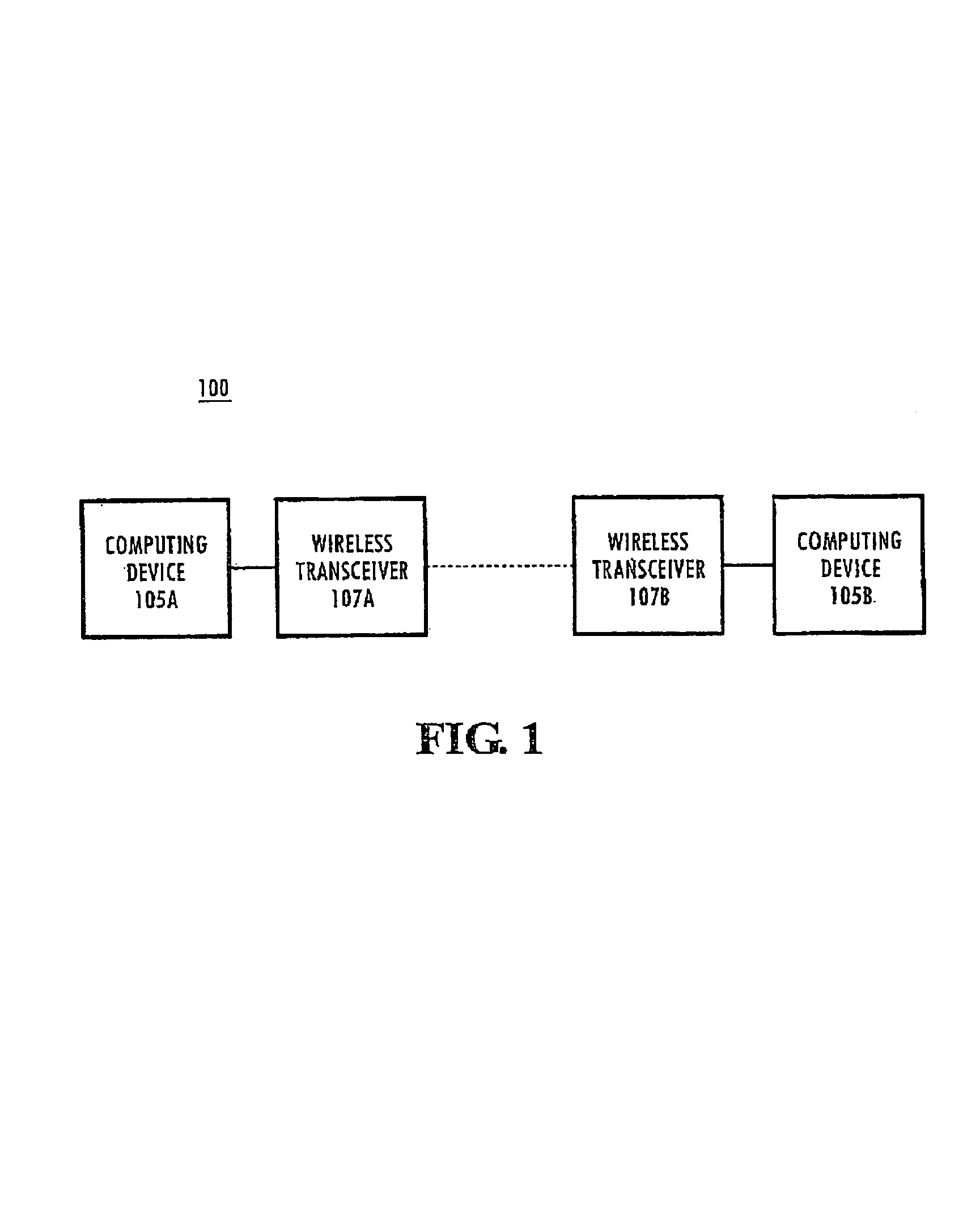
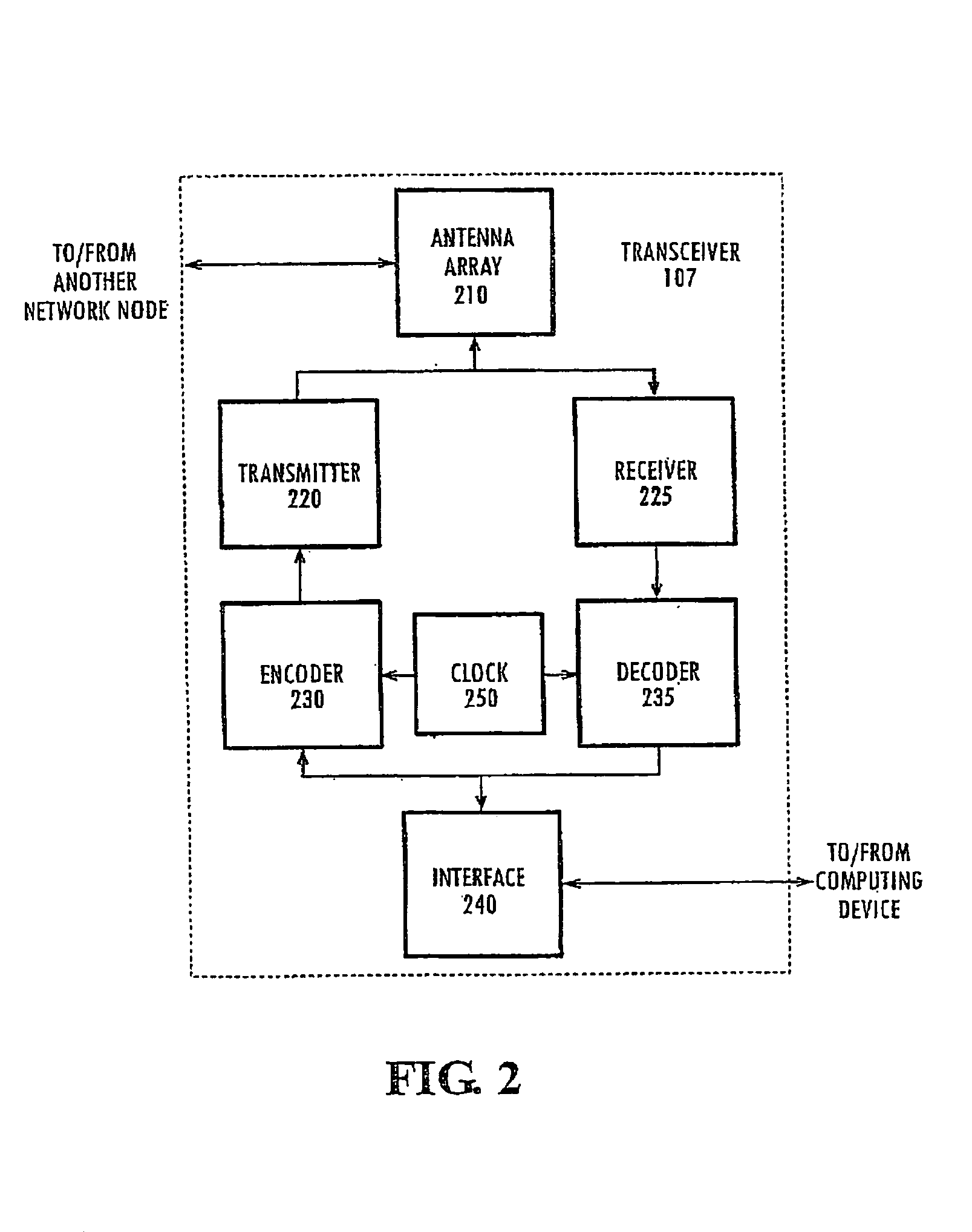
[0029]FIG. 1 illustrates a WLAN system 100 of an embodiment of the present invention. The system 100 includes a computing device 105A, a wireless transceiver 107A, a wireless transceiver 107B and a computing device 105B. Computing device 105A is coupled to wireless transceiver 107A, which together serve as a node on WLAN system 100. Computing device 105B is coupled to wireless transceiver 107B and together represent a second node on the network system 100. Computing device 105A communicates with computing device 105B by utilizing wireless transceiver 107A to transmit radio frequency (“RF”) frequency offset differential pulse position modulation (“FO-DPPM”) signals to wireless transceiver 107B, ...


PUM


Abstract

The present invention provides such a need by utilizing a frequency offset differential pulse position modulation scheme to transmit data between computing devices within a wireless network system. The differential pulse position modulation component of the scheme enables the present invention to provide relative immunity to interference for the system. In particular, such immunity from interference is achieved by utilizing a blanking time between pulse positions, which is large enough to allow the interference between frequency offset-differential pulse position modulation pulses to subside. The frequency offset component of the scheme enables the system to utilize multiple frequency channels to enable the system to achieve higher data rates. In particular, by utilizing a time offset between the frequency channels, the blanking time can be reduced, thereby increasing the amount of data that can be transmitted with a set period of time.

Description

RELATED APPLICATION[0001]This application is a continuation of U.S. application Ser. No. 09 / 500,750, filed on Feb. 8, 2000, and entitled “Frequency Offset Differential Pulse Position Modulation, now U.S. Pat. No. 6,711,122, which claims the benefit under 35 U.S.C. .sctn. 119(e) of U.S. Provisional Application Ser. No. 60 / 119,225, filed on Feb. 8, 1999, and entitled “Frequency Offset Differential Pulse Position Modulation Scheme,” having common Inventorship and assignee.BACKGROUND OF INVENTION[0002]1. Field of Technology[0003]The present invention generally relates to computer networks and, more particularly, to wireless networking.[0004]2. Description of Related Art[0005]Throughout the 1980s, local area networks (“LANs”) emerged as a new technology market. Aided by technology that allowed LANs to operate over the structured unshielded twisted pair telephone wire already installed in most buildings, the networking market has become a $7 billion a year business. Unfortunately, as orga...

Claims


Application Information

Patent Timeline
Patent Type & Authority Patents(United States)
IPC IPC(8): H04J9/00H04B14/02H04L1/16H04L1/18H04L5/06H04L12/28H04L12/56H04L25/49H04L27/26
CPCH04B14/026H04B14/066H04L1/1685H04L1/188H04L25/4902H04L27/2601H04W16/14H04L5/06H04L1/1887H04W84/18H04W36/06
Inventor LANGLEY, JOHN B.MANCUSI, MICHAEL
Owner RADIOLAN
Why Eureka
Try Eureka