GPS does not have the calibration, alignment, and maintenance requirements of conventional inertial measuring units, and is available 24 hours per day on a worldwide basis.
One critical limitation of these GPS systems is it requires the beacons to be in direct line-of-
sight (LOS) of the
receiver.
In other words, if the
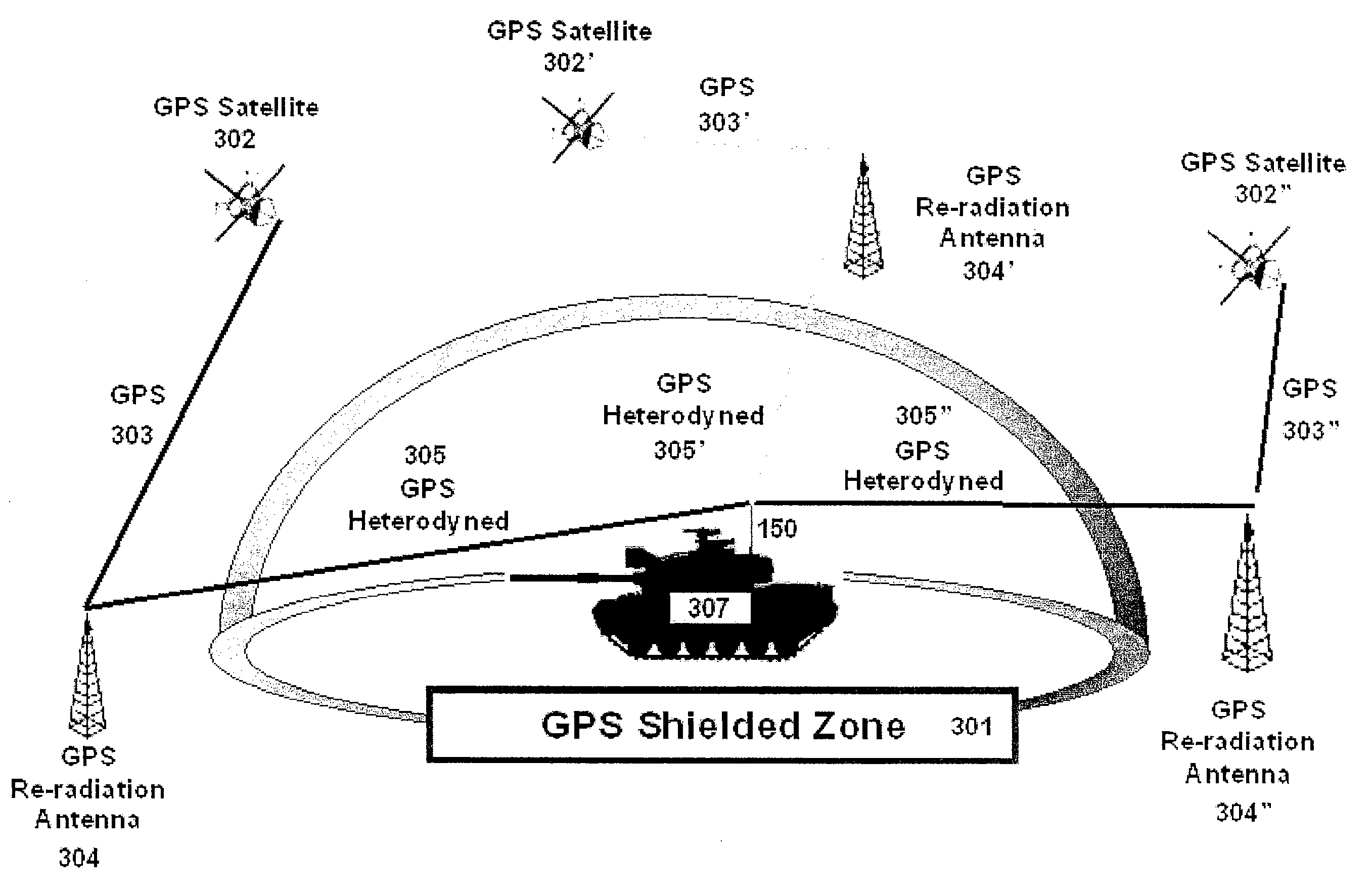
GPS receiver is used in heavily forested areas, in steep and narrow canyons, within a structure, adjacent to the outer walls of buildings, or various other line-of-sight barriers (LSB) or other shielded environments where
GPS signals may be jammed or spoofed, the
receiver will be unable to obtain a good repeatable reading, or in many cases, any reading at all.
Operating within a line-of-sight barrier (LSB) places fundamental limitations on the performance of radio positioning / navigation systems.
The existence of multi-path with different
time delays, gives rise to complex, time-varying transmission channels.
Signals can be received within a line-of-sight barrier (LSB), however to date, the equipment required to mitigate and correct for multi-path remains complex, sophisticated and the process is not repeatable.
These multi-path problems, in effect, limit the practical commercial use of
radio transmission of positioning / navigation data within a line-of-sight barrier (LSB).
Another dilemma associated with
radio transmission of positioning / navigation data within a line-of-sight barrier (LSB) is a phenomenon known as the “near-far” problem.
The near-far problem is due to simultaneous
broadcasting of signals from multiple broadcast antennae.
This problem arises because of the large variation of the user-to-broadcast antennae range.
On the other hand in a local
system, the broadcast antenna power from broadcast antennae varies a great deal, due to the inverse proportion to the square of the receiver's distance from the broadcast antennae, and can overwhelm other incoming signals.
Although there have been attempts to use radio positioning / navigation signals within a line-of-site barrier, to date the use of this technology is commercially impractical because of the problems described in the previous discussions.
The purpose of this type of jamming is to block out reception of transmitted signals and to cause a nuisance to the receiving operator.
Radar jamming is the intentional emmission of
radio frequency signals to interfere with the operation of a
radar by saturating its receiver with false information.
Noise jamming attempts to
mask the presence of targets by substantially adding to the level of thermal
noise received by the
radar.
Information that has appeared in the online
hacker magazine Phrack, potentially puts GPS devices used for commercial navigation and military operations at risk, authorities said.
Hasik said that while the Phrack jammer is targeted at civil
GPS signals, known as the C / A code, it could also threaten
military systems, since “almost all military GPS receivers must first acquire the C / A
signal” before locking onto the military
signal, known as the P(Y) code.
Hasik said that GPS receivers are especially vulnerable to jamming because of low
signal strength after traveling through space from
GPS satellites orbiting 12,000 miles above the earth.
Still, Defense officials viewed the Phrack article with concern.
As a result, the carrier and jamming signal beat and make impossible reception of data by the correlator.
Therefore, GPS are highly susceptible to a jamming signal based on a CW
sine wave.
Thus, both the civilian and military channels can be jammed without knowledge of GPS codes.
Although the GPS spread-spectrum signal offers some inherent antijam protection, an
adversary who is determined to negate a GPS system need only generate a jamming signal with enough power and suitable temporal /
spectral signature to deny the use of GPS throughout a given
threat area.
In addition, a controlled reception pattern antenna can only counter a limited number of jammers, as it eventually runs out of “
degrees of freedom” or antijamming options when the number of spatially distributed jammers grows too great.
Although the GPS Modernization program will increase
satellite power, this approach alone will not provide the entire antijam performance that is required.
No one method is right for all circumstances because each application presents its own unique requirements and constraints.
Moreover, a given technique may be effective against a particular class of threats, but may not necessarily address all threats.
For example, an adaptive
narrowband filter is effective against a jammer that has some repetitive or predictable signal structure, but is ineffective against a
broadband noise jammer, whose signal cannot be predicted from previous samples.
Likewise, spatial adaptive antenna arrays are effective against a limited number of
broadband noise and structured signal jammers, but eventually run out of
degrees of freedom as the number of jammers increases.

