CT integrated respiratory monitor

Inactive Publication Date: 2007-02-27
KONINKLIJKE PHILIPS ELECTRONICS NV
View PDF19 Cites 52 Cited by
  • Summary
  • Abstract
  • Description
  • Claims
  • Application Information

AI Technical Summary

Benefits of technology

[0018]One primary advantage of the invention is the association of respiratory parameters recorded during patient imaging scans together with the patient volumetric image data. In that way, radiologists and interventionists can use the respiratory parameters in determining whether the image of the patient is accurate and in making other medical and technical determinations. The parameters and image data are stored in a memory for later retrieval as needed. The association of the respiratory parameters directly with the image data significantly improves the integrity of the imaging system and thus enhances overall medical treatment of the patient.
[0019]Another significant advantage of the invention is that it used to help patients maintain a breath hold during CT scanning. The patient display showing patient breath hold levels is intuitive and relaxing to the patient. Using this system

Problems solved by technology

However, the increased Z-axis resolution of these CT scanners is not fully utilized when artifacts arising from respiratory motion are introduced into the image.
However, in spite of a training period, some patients (about 20%) have difficulty either initiating the breath hold when instructed to do so at the start of the scan or have difficulty holding their breath throughout the scan.
Images acquired under those circumstances suffer from motion artifacts.
Another problem arising from procedures requiring breath holding is the relative inability to provide pre-operative and intra-operative breath hold congruency.
More particularly, breath holds during the pre-operative planning phase and during the intra-operative phase of interventional treatments can vary leading to gross inaccuracy in instrument position or object placement within the patient.
Still further, another shortcoming of prior systems is the inability to co

Method used


Image

  • CT integrated respiratory monitor
  • CT integrated respiratory monitor
  • CT integrated respiratory monitor

Examples


Example

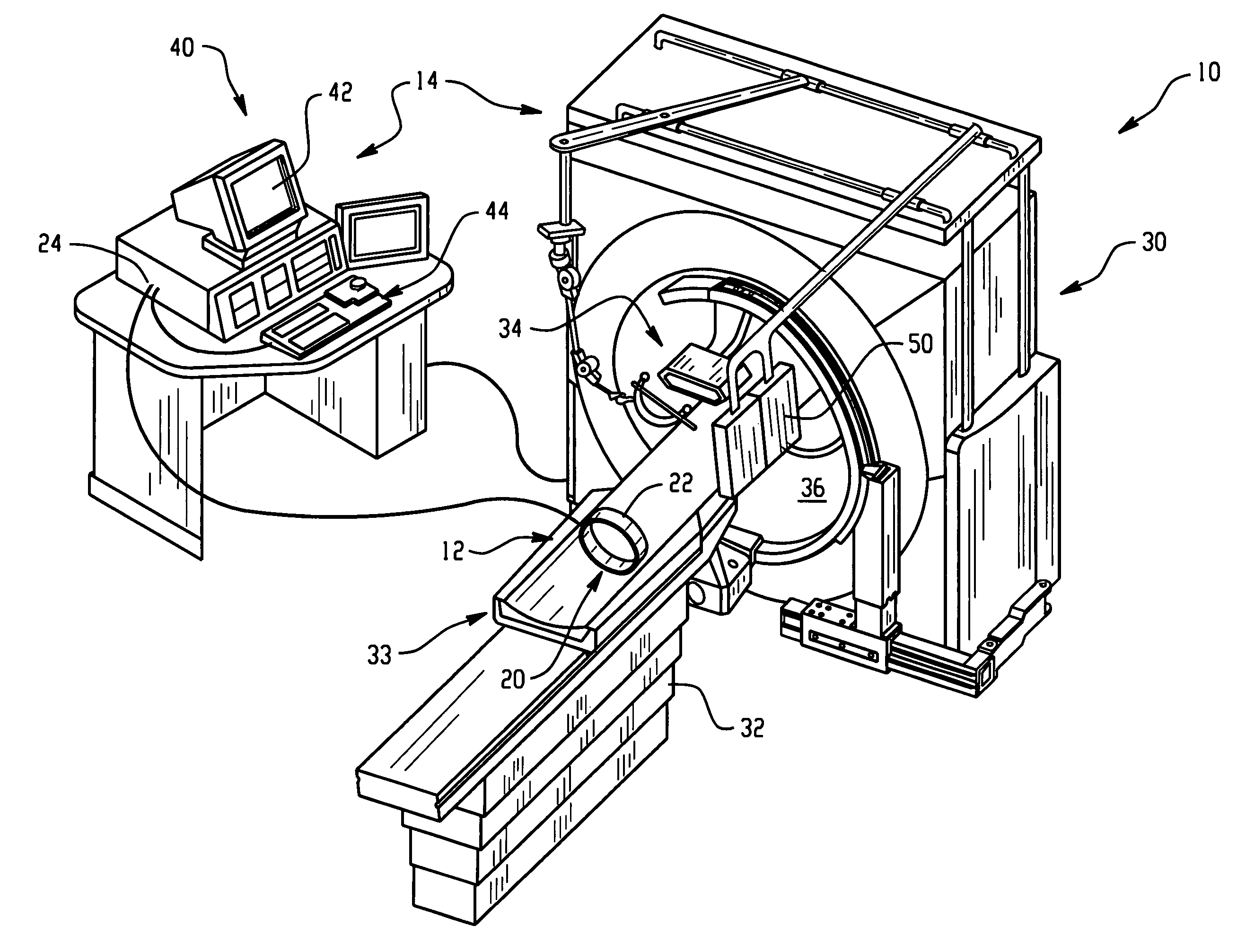
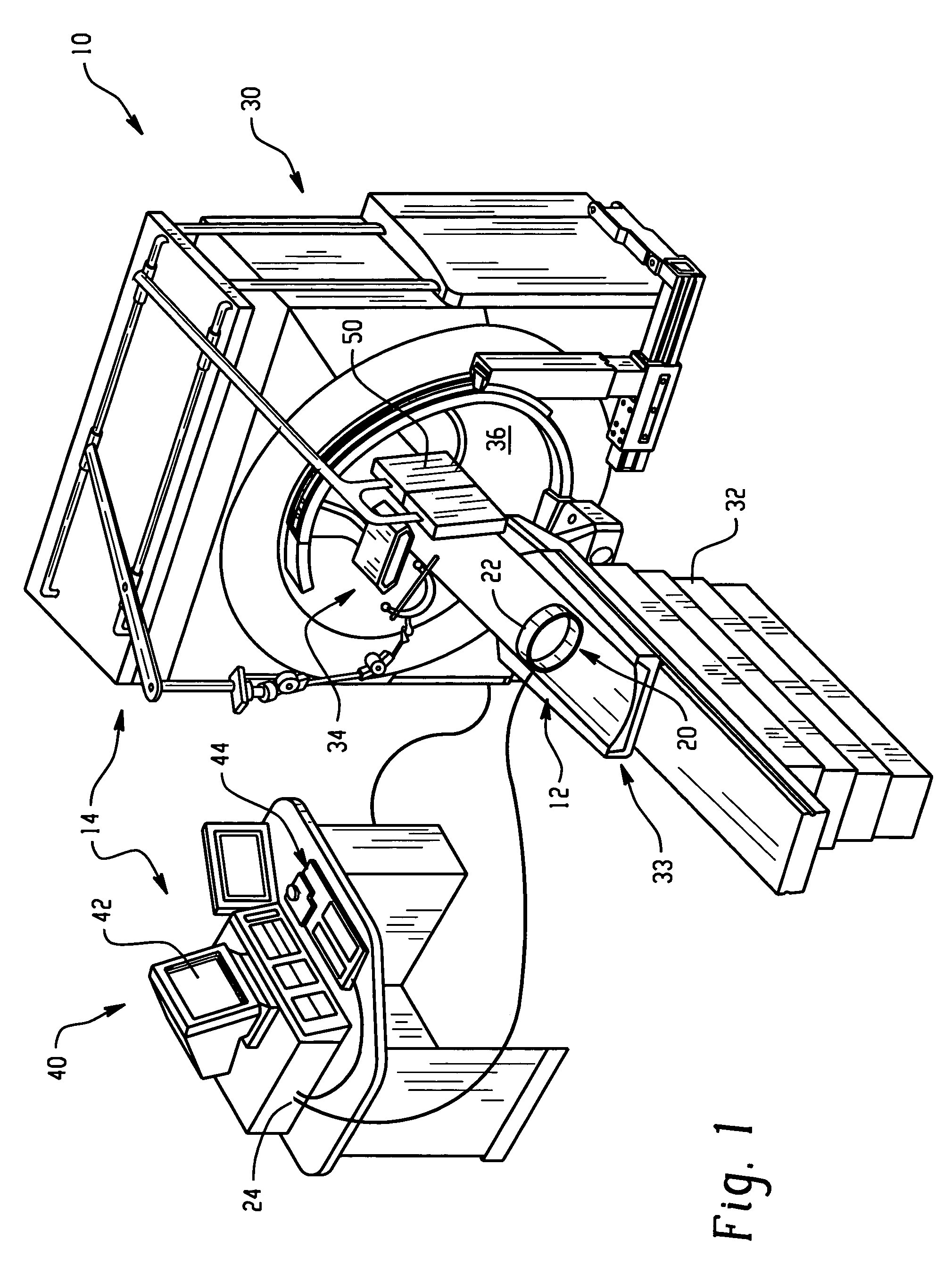
[0035]Referring now to the drawings wherein the showings are for purposes of illustrating the preferred embodiments of the invention only and not for purposes of limiting same, with reference first to FIG. 1, an integrated apparatus 10 includes a respiratory monitor system 12 and a CT imaging device 14. The integrated apparatus 10 is particularly well suited for planning and executing minimally invasive surgical procedures for in-vivo placement of instruments and / or objects within a patient during one or more breath holds.

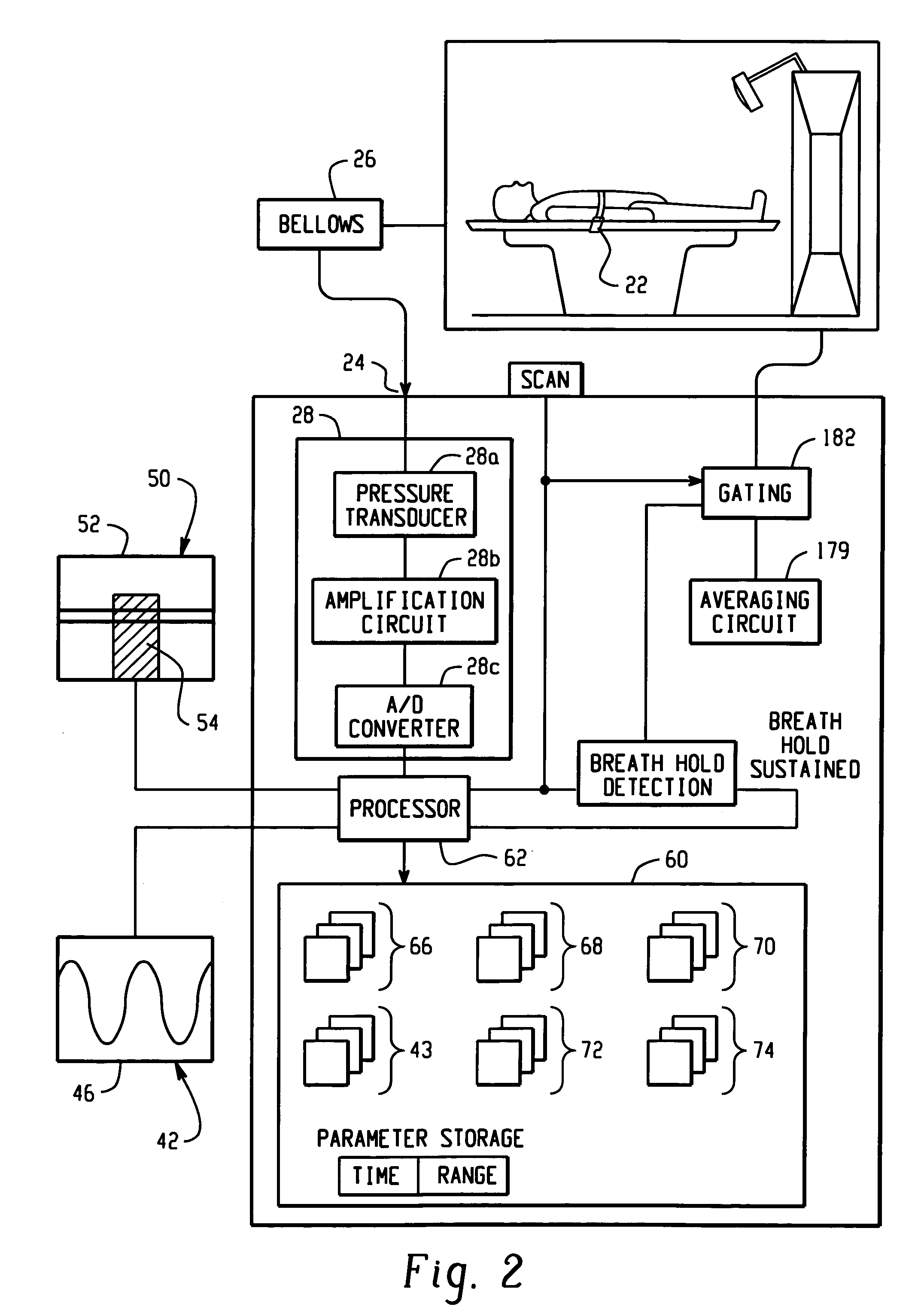
[0036]The respiratory monitor system 12 includes a respiratory sensor 20 preferably formed as a belt 22 adapted for attachment around the abdomen or chest of a patient. In its preferred form, the respiratory sensor 20 includes an air bellows sensor and pressure transducer (not shown) for generating a signal corresponding to the displacement of a patient's abdomen during respiration. The respiratory sensor 20 is attached to the imaging device 14 at a suitable electr...


PUM


Abstract

An integrated respiratory monitor and imaging device apparatus (10) is provided. The apparatus is useful for establishing pre-operative and intra-operative breath hold congruency in patients and for other interventional work. The apparatus (10) includes a respiratory monitor system (12) and an imaging device (14). The respiratory monitor system is adapted to engage a patient and generate a respiratory signal representative of a breath hold level of the patient during a breath hold. The imaging device (14) is adapted to scan the patient during the breath hold and generate a volumetric image data set of the patient. The respiratory sensor and imaging device are operatively connected to associate the respiratory signal representative of the breath hold level of the patient together with the volumetric image data set of the patient. A data storage device (64) is provided for storing a set of respiratory signals in association with a corresponding set of volumetric image data sets in the subject apparatus (10). A scanner gating function is provided to center the image acquisition time at selected points in the respiratory cycle such as at a minimum to minimize motion artifacts in the resultant image.

Description

CROSS-REFERENCE TO RELATED APPLICATION[0001]This application claims the benefit of U.S. Provisional Application Ser. No. 60 / 369,485 filed Apr. 3, 2002.BACKGROUND OF THE INVENTION[0002]The present invention relates to the art of interactive image-guided surgery and interactive surgical procedures which require patient breath holding or breathing control. It finds particular application in conjunction with planning and implementation stages of minimally invasive stereotactic surgical procedures performed in CT imaging systems using a localization device to orient surgical tools such as biopsy or brachytherapy needles or the like for tissue sampling or planning or placement of objects or instruments within the body of a patient, and will be described with particular reference thereto. It is to be appreciated, however, that the invention is also applicable to a wide range of imaging equipment and techniques, for example ultrasonic and magnetic resonance imaging devices, and to a broad r...

Claims


Application Information

Patent Timeline
IPC IPC(8): A61M16/00A62B7/00F16K31/02A61B5/08A61B5/11A61B5/113A61B6/00A61B6/03
CPCA61B5/1135A61B6/541Y10S128/916
Inventor YANOF, JEFFREY H.JOHNSON, PETER C.
Owner KONINKLIJKE PHILIPS ELECTRONICS NV
Why Eureka
Try Eureka