Plasma display panel and video display system employing same

a technology of display panel and video display system, which is applied in the direction of static indicating devices, instruments, gas-filled discharge tubes, etc., can solve the problems of difficult fabrication of high barrier ribs and reduced contrast ratio of light-room displays, so as to increase the discharge space, improve and improve the effect of brightness and luminous efficacy

Inactive Publication Date: 2007-02-27
HITACHI LTD
View PDF11 Cites 1 Cited by
  • Summary
  • Abstract
  • Description
  • Claims
  • Application Information

AI Technical Summary

Benefits of technology

[0021]In the case of the ac surface-discharge type, since the discharge for producing a display is generated along a surface, improvement of brightness and luminous efficacy requires an increase in the discharge space. The discharge space can be made larger by increasing its aperture ratio, where the aperture ratio is defined as a ratio of an area of a window portion of the front substrate through which display-forming visible light is irradiated into the viewing space, that is, an area of an aperture, to an area of a projection of the display discharge space onto the display surface. However, an increase in the aperture ratio decreases an area usable for a black matrix which fills spaces between the apertures with black opaque material, and a problem arises in that a light-room display contrast ratio is reduced.
[0024]In an embodiment of the present invention, the light-room display contrast is increased (1) by increasing the discharge space by adopting a two-electrode discharge PDP of the ac vertical-discharge type, and thereby improving the brightness of generated light and the luminous efficacy; and also (2) by limiting the aperture ratio to 40%, and thereby disposing black opaque material in areas other than the apertures. In order to make the discharge space larger, the height of the barrier ribs is selected to be 0.2 mm or more, and a layer of the barrier ribs is fabricated separately from the front and rear plates. Phosphor films are coated on the layer of the barrier ribs before the layer of the barrier ribs is attached to the front or rear plate, and consequently, this configuration can suppress degradation of the protective layer which is caused in its conventional fabrication process.
[0046]The present invention is capable of realizing a plasma panel display which exhibits a high luminous efficacy in terms of a display set (which provides a high-brightness image display with a low power consumption) and a high light-room display contrast.

Problems solved by technology

However, an increase in the aperture ratio decreases an area usable for a black matrix which fills spaces between the apertures with black opaque material, and a problem arises in that a light-room display contrast ratio is reduced.
However, in that case, the height of barrier ribs surrounding the discharge space needs to be selected to be greater, and consequently, it makes fabrication of the high barrier ribs difficult by using a process which fabricates the barrier ribs on the front or rear plate.

Method used


Image

  • Plasma display panel and video display system employing same
  • Plasma display panel and video display system employing same
  • Plasma display panel and video display system employing same

Examples


embodiment 1

[0071

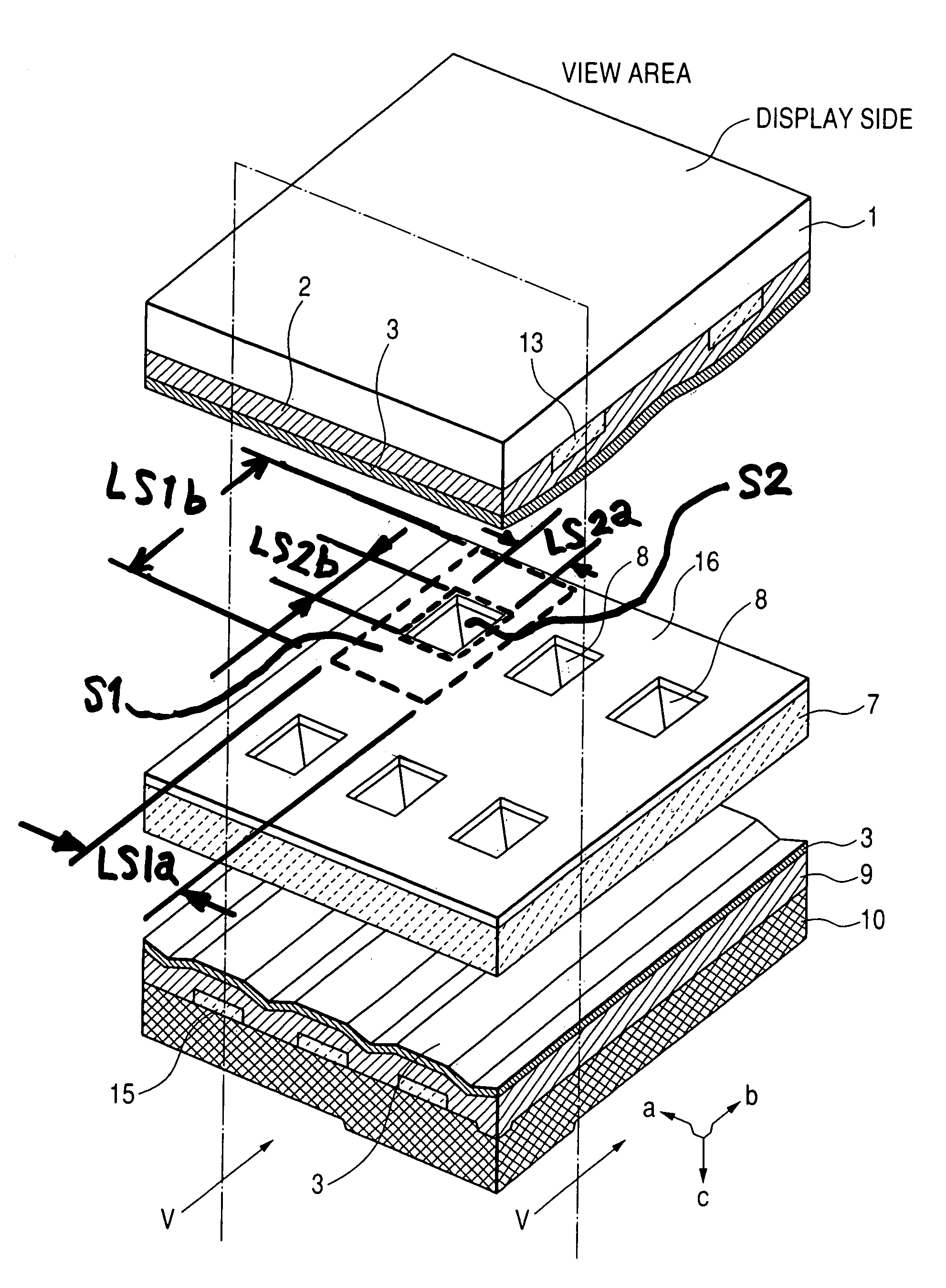
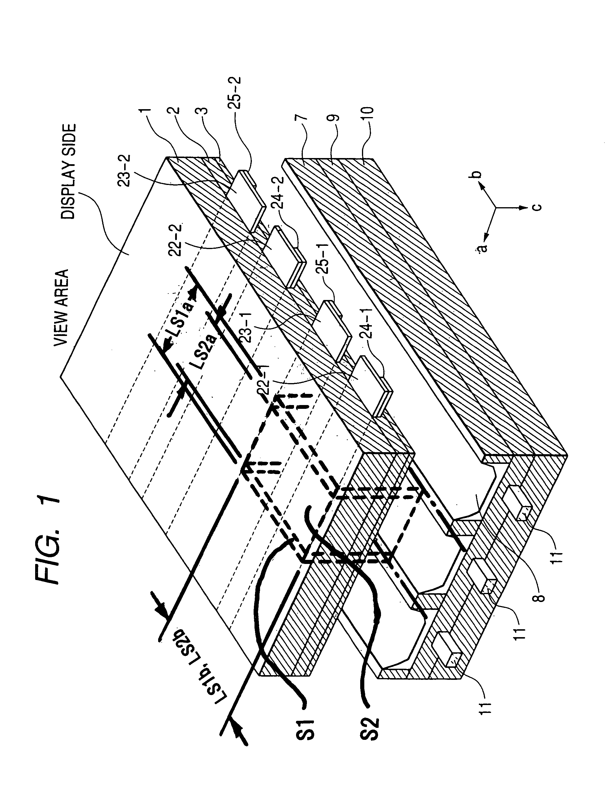
[0072]FIG. 4(a) is an exploded perspective view of an embodiment of the plasma display panel in accordance with the present invention. Scan electrodes 13 are fabricated so as to extend in a direction of an arrow b on a front plate 1, a dielectric 2 is disposed to cover the scan electrodes 13, and then a protective layer 3 is disposed to cover the dielectric 2.

[0073]An integral structure comprised of the front substrate 1, the scan electrodes 13, the dielectric 2 and the protective layer 3 is hereinafter referred to as a front plate. A barrier rib plate 7 is provided with apertures in the form of stripes or grids. Phosphors 8 are coated on the wall surfaces of the apertures, and a black matrix 16 is formed on the top surface of the barrier rib plate 7. FIG. 4(a) is an exploded perspective view of an example of the PDP employing the barrier rib plate 7 provided with the apertures in the form of stripes, and FIG. 4(b) is an exploded perspective view of an example of the PDP employ...

embodiment 2

[0083

[0084]Before explaining this embodiment, the difference between the ac surface-discharge type plasma panel and the ac vertical-discharge type plasma panel will be explained by reference to FIGS. 8 to 11.

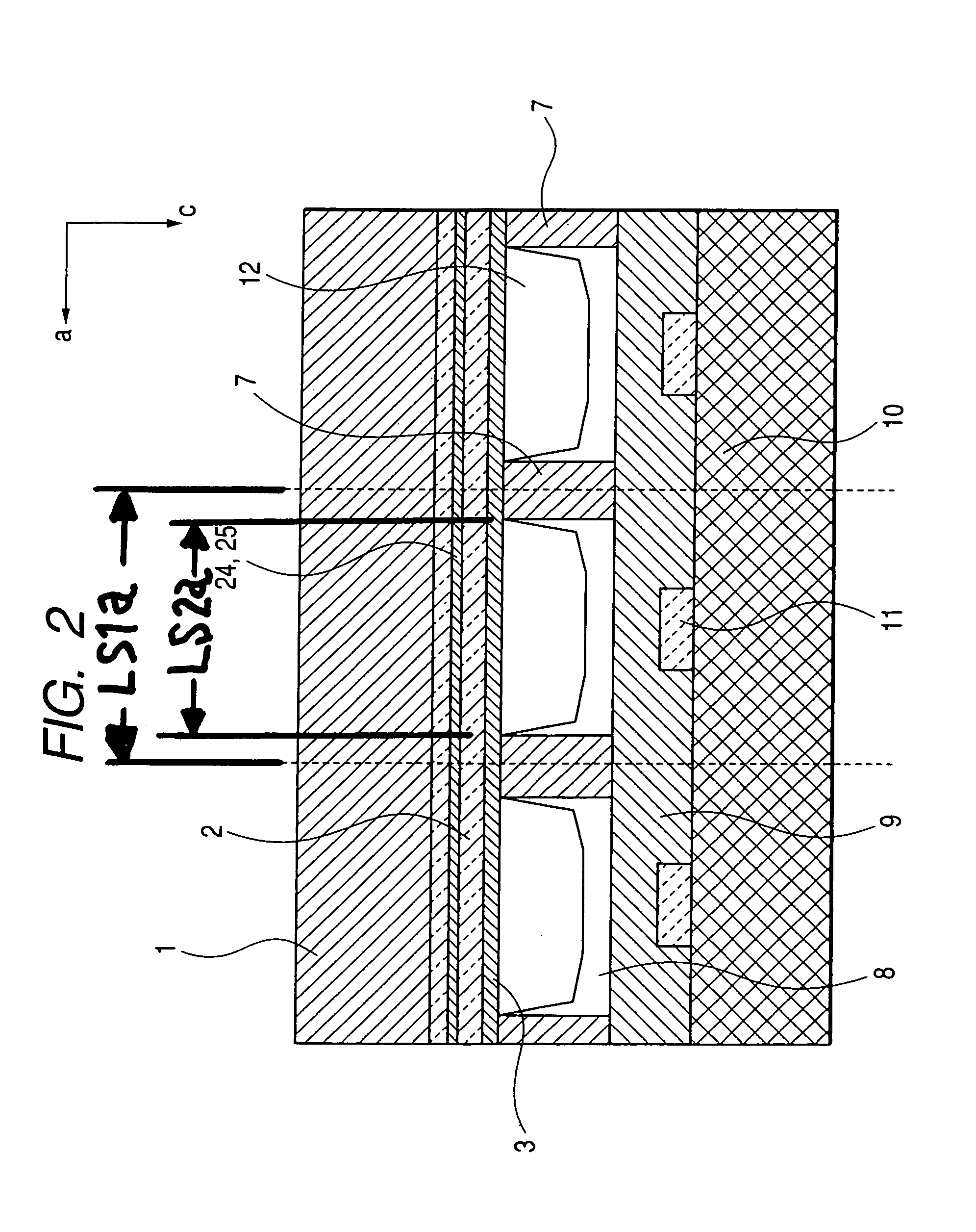
[0085]FIG. 8 is a cross-sectional view of one pixel comprised of three discharge cells for three primary colors of red (R), green (G) and blue (B), respectively, in the ac surface-discharge type plasma panel. FIG. 9 is a plan view looking down at an arrangement of the barrier rib plate 7 and phosphors 8 of the ac surface-discharge type plasma panel of FIG. 8.

[0086]FIG. 10 is a cross-sectional view of one pixel comprised of three discharge cells for three primary colors of red (R), green (G) and blue (B), respectively, in the ac vertical-discharge type plasma panel. FIG. 11 is a plan view looking down at an arrangement of the barrier rib plate 7 and phosphors 8 of the ac vertical-discharge type plasma panel of FIG. 10. The ac vertical-discharge type plasma panel makes possible re...

embodiment 3

[0090

[0091]Although the apertures provided in the barrier rib plate 7 are in the forms of stripes (or bands) in the embodiments explained in connection with FIGS. 10 to 15, the barrier rib plate 7 in the form of grids or boxes can also provides the same advantages. FIG. 16 is a plan view looking down at an embodiment employing such a barrier rib plate. In this case, the aperture ratio can be made smaller, and the light-room display contrast can be improved. FIG. 17 is a plan view of an example of a plasma panel having disposed a visible-light non-reflective layer 17 on the surfaces of the front plate 10 and the data electrodes 15 visible within the discharge cells from the viewing space in the case of FIG. 16.


PUM


Abstract

A plasma display panel includes plural discharge cells and a barrier rib layer which defines the discharge cells. Each discharge cells has two opposing electrodes on front and rear substrates, respectively, for generating discharge therebetween, discharge gas and phosphor films. The barrier rib layer is fabricated as a sheet separate from the substrates, is provided with openings each forming a discharge space, and is sandwiched between the substrates. The following relationships are satisfied: 0.1≦S2 / S1≦0.4; 100 Torr ×mm≦pd≦400 Torr×mm; and 0.2 mm≦d, where S1 is an area of a projection of a space occupied by one discharge cell onto the front substrate, S2 is an area of a portion of the front substrate for projecting light from the discharge cell, p is a pressure of the discharge gas, and d is a distance between the electrodes.

Description

CLAIM OF PRIORITY[0001]The present application claims priority from Japanese application serial no. 2004-257253, filed on Sep. 3, 2004, the content of which is hereby incorporated by reference into this application.BACKGROUND OF THE INVENTION[0002]1. Field of the Invention[0003]The present invention relates to a plasma display panel (hereinafter also referred to as a plasma panel or a PDP), and in particular to a structure of a plasma panel capable of improving a light-room contrast and realizing high luminous efficacy and high-quality display images, a method of manufacturing the plasma panel, a method of driving the plasma panel, and a plasma display apparatus including a driving device in addition to the plasma panel.[0004]2. Description of Prior Art[0005]Recently, plasma display devices have been expected as promising large-size thin color display devices. More specifically, since an ac surface-discharge type PDP generates discharges between electrodes disposed on the same subst...

Claims


Application Information

Patent Timeline
Patent Type & Authority Patents(United States)
IPC IPC(8): H01J17/49H01J11/12H01J11/22H01J11/24H01J11/34H01J11/36H01J11/42H01J11/44H01J11/50
CPCH01J11/36H01J11/42H01J11/44H01J2211/444H01J2211/361H01J2211/442H01J1/88H01J17/492
Inventor MIYAKE, TATSUYASUZUKI, KEIZOSHIIKI, MASATOSHIFUJITA, TSUYOSHITSUCHIDA, SEIICHI
Owner HITACHI LTD
Why Eureka
Try Eureka