Heat sink vacuum packaging procedure

a vacuum packaging and heat sink technology, applied in indirect heat exchangers, manufacturing tools, light and heating equipment, etc., can solve the problems of high manufacturing cost and affect the quality of heat sinks, and achieve the effects of reducing manufacturing costs, reducing labor costs, and eliminating drawbacks

Inactive Publication Date: 2007-03-06
TATUNG COMPANY
View PDF5 Cites 1 Cited by
  • Summary
  • Abstract
  • Description
  • Claims
  • Application Information

AI Technical Summary

Benefits of technology

[0005]The present invention has been accomplished to provide a heat sink vacuum packaging procedure, which eliminates the drawbacks of the aforesaid conventional method. It is the main object of the present invention to provide a heat sink vacuum packaging procedure, which requires less time and labor, reduces the heat sink manufacturing cost, and improves the heat sink quality.
[0013]As indicated, the invention employs a continuous flow to rapidly achieve the packaging of the heat sink. During packaging, it is not necessary to treat the heat sink upper cover or heat sink bottom cover with any additional processing process such as conventional drilling, welding, vacuum pumping. Therefore, the invention shortens the packaging of the heat sink, saves much labor and time, and reduces the manufacturing cost of the heat sink. Further, because no welding process is needed in the aforesaid packaging procedure, the invention eliminates the problem of accidentally flowing of tin solder into the inside of the heat sink during packaging, improving the quality of the heat sink.

Problems solved by technology

The aforesaid conventional steam chamber type heat sink packaging procedure is complicated and requires much labor and time, resulting in high manufacturing cost.
Further, tin solder may flow into the inside of the heat sink during welding, affecting the quality of the heat sink.

Method used


Image

  • Heat sink vacuum packaging procedure
  • Heat sink vacuum packaging procedure
  • Heat sink vacuum packaging procedure

Examples


Embodiment Construction

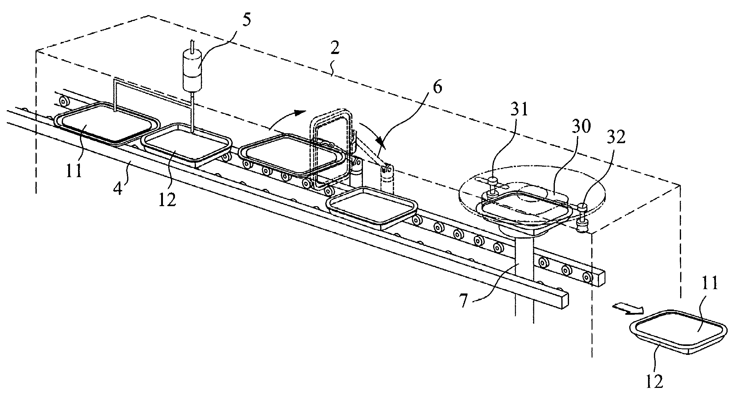
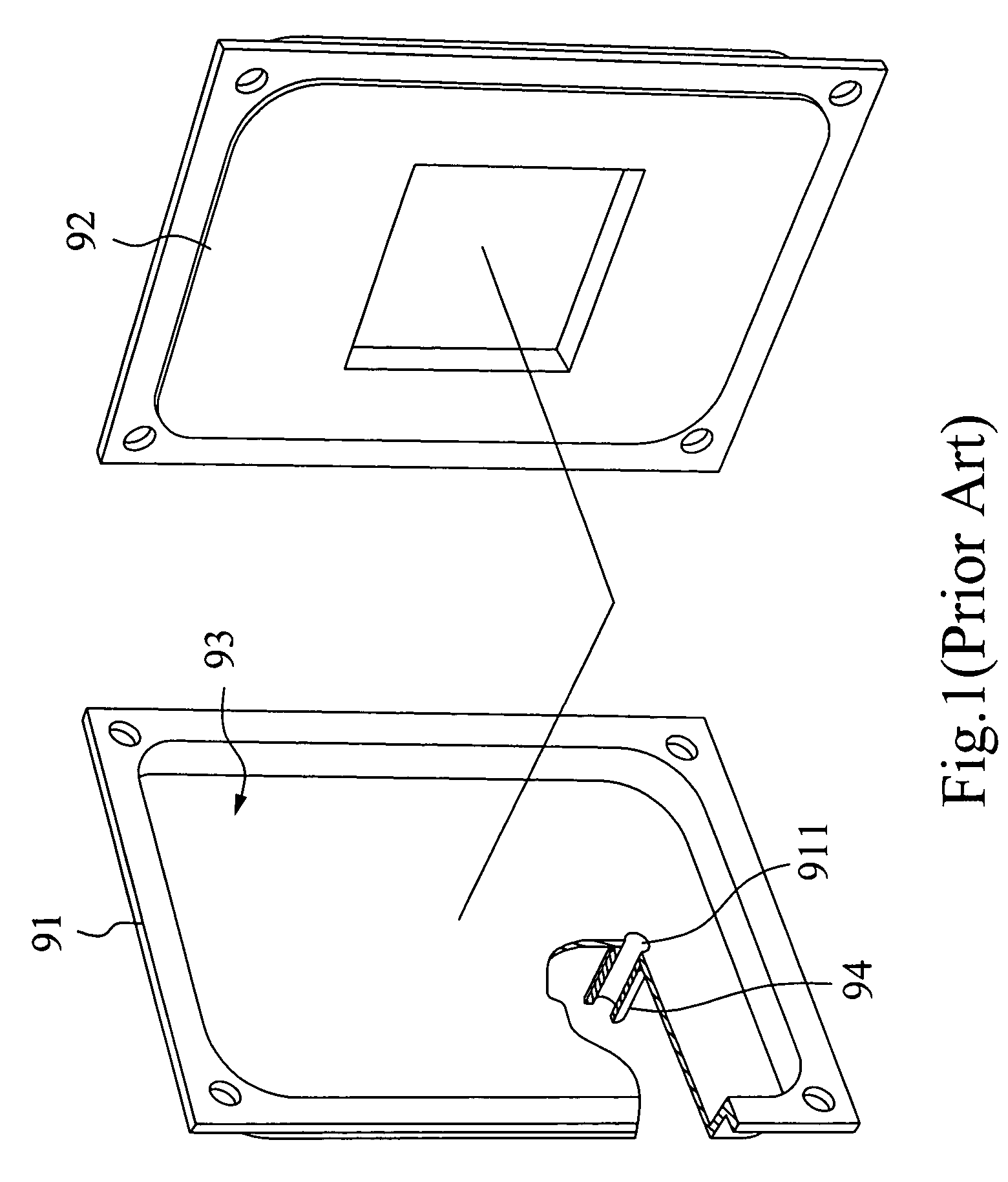
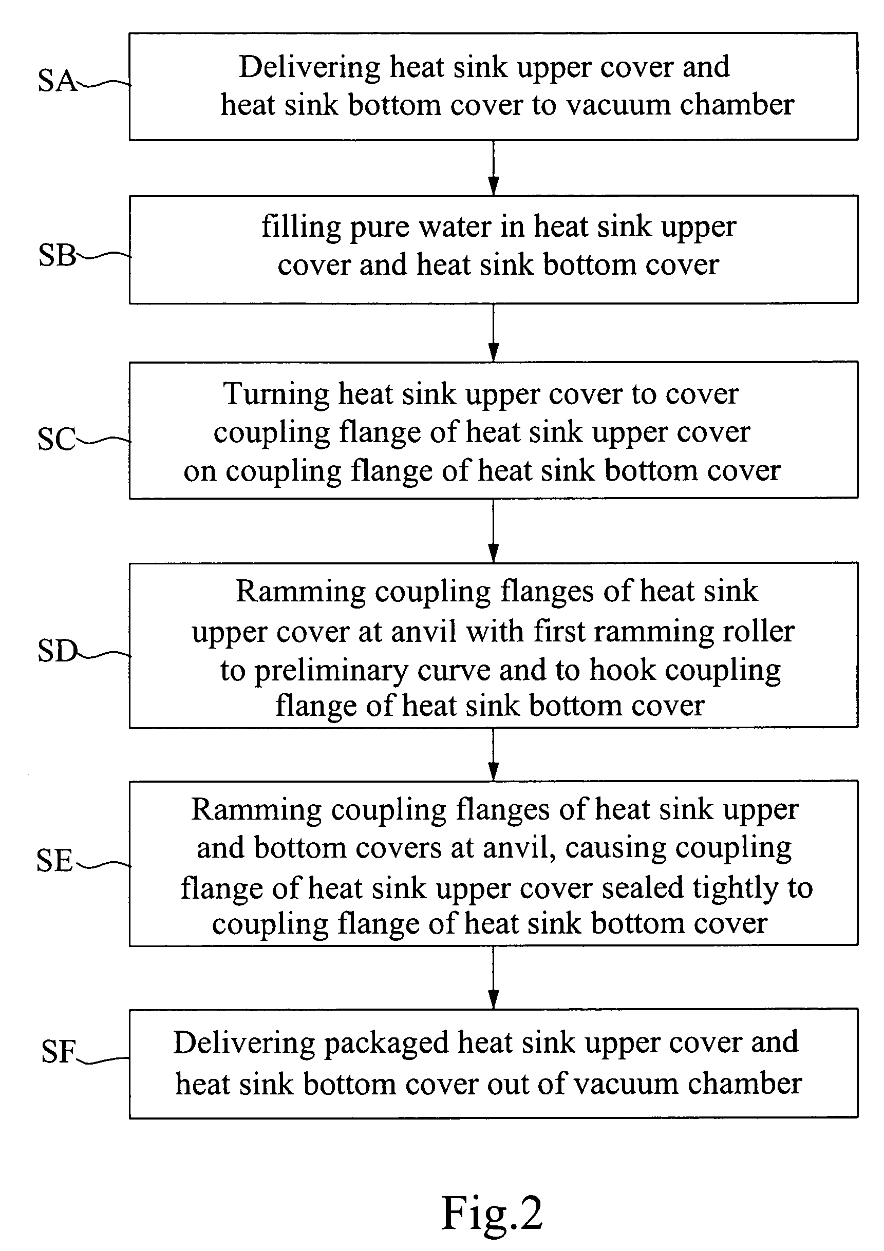
[0021]The present invention will now be described by way of example with reference to FIGS. 2 and 3, at first, use a conveyer 4 to carry a heat sink upper cover 11 and a heat sink bottom cover 12 to a vacuum chamber 2 (SA). The heat sink upper cover 11 and the heat sink bottom cover 12 have a respective peripheral coupling flange 111 or 121. These coupling flanges 111 and 121 both have a U-shaped profile concaved downwardly (see FIG. 4).

[0022]After the heat sink upper cover 11 and the heat sink bottom cover 12 have been delivered to the vacuum chamber 2, a pure water injector 5 is operated to inject pure water into the inside space of the heat sink upper cover 11 and the inside space of the heat sink bottom cover 12 (SB). At this time, pure water is adhered to the inside of the heat sink upper cover 11 and the heat sink bottom cover 12 by means of the capillary cohesive force of the heat sink upper cover 11 and the heat sink bottom cover 12.

[0023]Referring to FIGS. 2–4 again, after ...


PUM

PropertyMeasurementUnit
capillary cohesive forceaaaaaaaaaa
timeaaaaaaaaaa

Abstract

A heat sink vacuum packaging procedure to rapidly complete the packaging of a heat sink without drilling, pipe welding, vacuum pumping, or other processes. Because the packaging procedure saves much time and labor, the manufacturing cost of the heat sink is relatively reduced. During packaging, no welding process is employed, therefore the invention prevents accidentally flowing of tin solder into the inside of the heat sink to affect the quality of the heat sink, and the quality of the heat sink is maintained.

Description

BACKGROUND OF THE INVENTION[0001]1. Field of the Invention[0002]The present invention relates to a heat sink vacuum packaging procedure and, more particularly, to a packaging procedure adapted to package a steam chamber type heat sink for use to dissipate heat from the CPU of a computer.[0003]2. Description of Related Art[0004]FIG. 1 is an exploded view of a conventional steam chamber type heat sink. According to a conventional packaging method, the heat sink upper cover 91 and the heat sink bottom cover 92 are abutted against each other and then peripherally sealed by welding, defining an enclosed chamber 93. Thereafter, a through hole 911 is formed in the heat sink upper cover 91 by drilling, and then a connector 94 is welded to the periphery of the through hole 911 and connected to a vacuum pump (not shown), which is operated to draw the enclosed chamber 93 into a vacuum status. At final, pure water is filled through the connector 94 into the enclosed chamber 93, and then the con...

Claims


Application Information

Patent Timeline
Patent Type & Authority Patents(United States)
IPC IPC(8): B21D53/02B21D39/02F28D15/02B21D51/32B21D53/04
CPCB21D51/32Y10T29/49993Y10T29/4935Y10T29/49918Y10T29/49915Y10T29/49917
Inventor CHIU, LIU-HOWU, CHANG-HUICHOU, MING-DERCHANG, CHEN-MING
Owner TATUNG COMPANY
Why Eureka
Try Eureka