Method for manufacturing a medical implant

a technology for medical implants and manufacturing methods, applied in applications, medical science, blood vessels, etc., can solve the problems of preventing the design of continuous structures, affecting the quality and cost of the final product, and the process can take a long tim

Inactive Publication Date: 2007-03-06
ANSON MEDICAL LTD
View PDF15 Cites 56 Cited by
  • Summary
  • Abstract
  • Description
  • Claims
  • Application Information

AI Technical Summary

Benefits of technology

[0022]In one embodiment a chain stitch sewing machine is employed in which a simple mechanism is used beneath the fabric to hook the single thread, which passes through the needle. The hooked thread is then pulled through with the subsequent stitch so that a continuous run of stitches is formed from a single thread. Chain stitch is associated with a tendency to fray or to come apart. As part of the sewing algorithm, the machine can be made to back-stitch or otherwise over-stitched to lock the stitch into place. Glues may also be used to stabilize the thread.
[0023]Other methods of stabilizing chain stitch can be employed such as the so-called double chain stitch in which a second thread is introduced. In one version of double chain stitch, alternate loops are formed from alternate threads. In another version, the second thread is pulled through the loops to lock them together. In a further modification to stabilize a chain stitch, a single chain stitch can be formed and upon withdrawing the needle it is rotated between half a turn and five turns to form a twist in the thread. This twist will resist the ‘fraying’ of the single chain stitch.

Problems solved by technology

Typically, tubular grafts are stitched by hand to metallic stent structures and this process can take a long time.
Other problems with the process include difficulties in controlling and assuring the quality and the cost of the final product.
This approach solves many of the issues associated with hand manufacturing but results in a seam and prevent some continuous structures from being designed.
This sewing machine could not be employed to stitch thread to the wall of a tubular graft, because the graft would not be sufficiently compliant to enable a folded section of graft to be sucked into the machine.
This means that movement of the needle independently of the shuttle is not possible for all degrees of freedom.
The apparatus is not suitable for sewing a tubular implant.

Method used


Image

  • Method for manufacturing a medical implant
  • Method for manufacturing a medical implant
  • Method for manufacturing a medical implant

Examples


Embodiment Construction

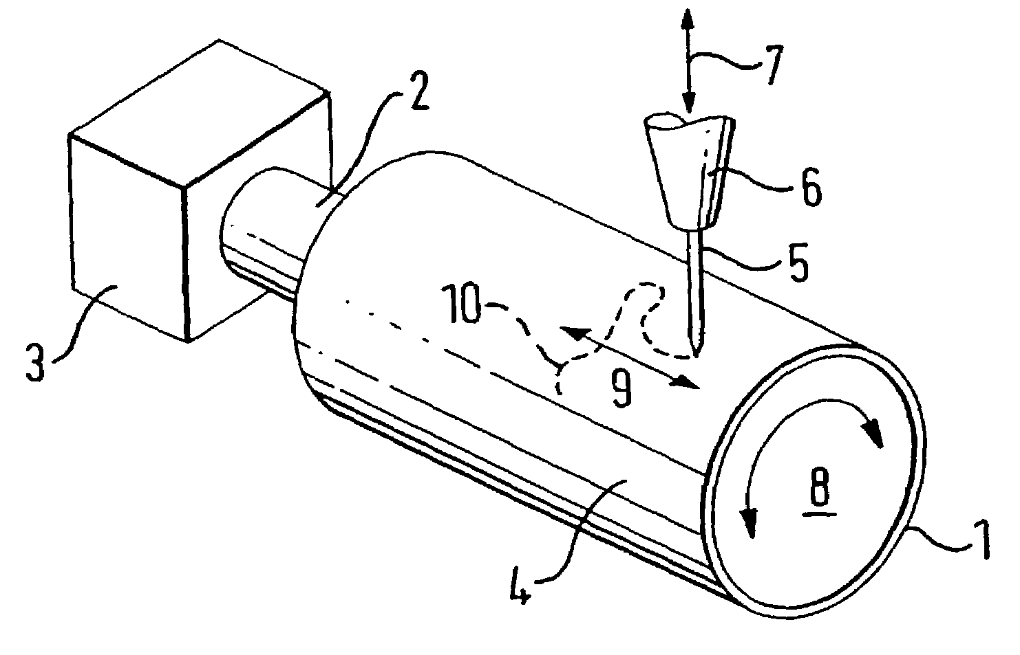
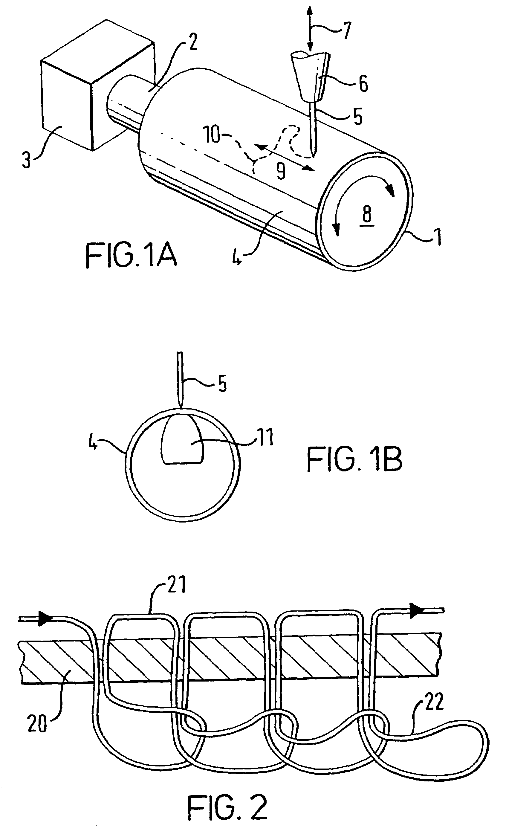
[0054]FIG. 1A shows a drum assembly 1 mounted on a rotor 2 which is driven by a drive assembly 3. A graft 4 is supported on drum assembly 1. Needle 5 is mounted on sewing machine head 6 above graft 4.

[0055]In operation, drive assembly 3 operates to rotate rotor 2, drum assembly 1 and graft 4 about the longitudinal axis of graft 4 as shown by arrow 8. Drive assembly 3 can also operate to translate graft 4 back and forth along its longitudinal axis as shown by arrow 9.

[0056]Sewing machine head 6 can be moved up and down relative to graft 4 as shown by arrow 7 by a drive system on the sewing machine (not shown). Thus a combination of these movements can be used to move needle 5 along the surface of graft 4 as shown by dotted line 10.

[0057]FIG. 1B shows an end-on view of the apparatus of FIG. 1A. Bobbin 11 can be seen inside graft 4 underneath needle 5. In operation, bobbin 11 can be moved back and forth along the longitudinal axis of graft 4 by a drive mechanism (not shown) in order to...


PUM

PropertyMeasurementUnit
diameteraaaaaaaaaa
diameteraaaaaaaaaa
diameteraaaaaaaaaa

Abstract

A method for stitching thread onto the wall of a tubular medical implant (preferably a graft) employs a sewing machine with an elongate bobbin or a needle on an elongate element, depending on whether it is desired to sew from the outside-in or the inside-out. A motor rotates and translates the implant, which is mounted on a hollow drum, relative to the needle.

Description

FIELD OF THE INVENTION[0001]The present invention relates to a method and apparatus for stitching thread to the wall of a tubular medical implant, and in particular to a method and apparatus for stitching thread to the wall of a graft, for example to form a graft-stent.BACKGROUND OF THE INVENTION[0002]Typically, tubular grafts are stitched by hand to metallic stent structures and this process can take a long time. Other problems with the process include difficulties in controlling and assuring the quality and the cost of the final product.[0003]An alternative solution has been described in WO 99 / 37242 (in the name of the present applicant) in which computerized embroidery is used to manufacture a flat-form device which is subsequently rolled into a tube. This approach solves many of the issues associated with hand manufacturing but results in a seam and prevent some continuous structures from being designed.[0004]GB 2165559 (University College London) discloses a sewing machine for ...

Claims


Application Information

Patent Timeline
Patent Type & Authority Patents(United States)
IPC IPC(8): D05B21/00A61F2/02D05B39/00A61F2/06A61B17/04A61F2/07A61F2/848A61F2/86A61L17/00
CPCA61F2/07A61F2/86A61F2220/0075Y10S623/901A61F2002/075
Inventor PHILLIPS, PETERBEATON, GAIL
Owner ANSON MEDICAL LTD
Why Eureka
Try Eureka