Monitoring terminal device

a terminal device and monitoring technology, applied in the direction of electric signalling details, fire alarms, instruments, etc., can solve the problems of inability to reduce the power consumption in the trigger receiving section, and the above-declared technology has a disadvantage, so as to achieve the effect of reducing power consumption

Inactive Publication Date: 2007-03-06
NEC CORP
View PDF2 Cites 12 Cited by
  • Summary
  • Abstract
  • Description
  • Claims
  • Application Information

AI Technical Summary

Benefits of technology

[0033]With the above configurations, including the sensor unit, the wireless transmitting unit, by wireless or alike, the power supply function (solar battery or a like), and the control function, when only the sensor unit detects state change of object to be monitored, the control unit and the wireless transmitting unit are started to transmit information. After completion of

Problems solved by technology

However, the above-disclosed technology has a disadvantage.
That is, in order to receive a trigger from the external device, a trigger receiving section

Method used


Image

  • Monitoring terminal device
  • Monitoring terminal device
  • Monitoring terminal device

Examples


first embodiment

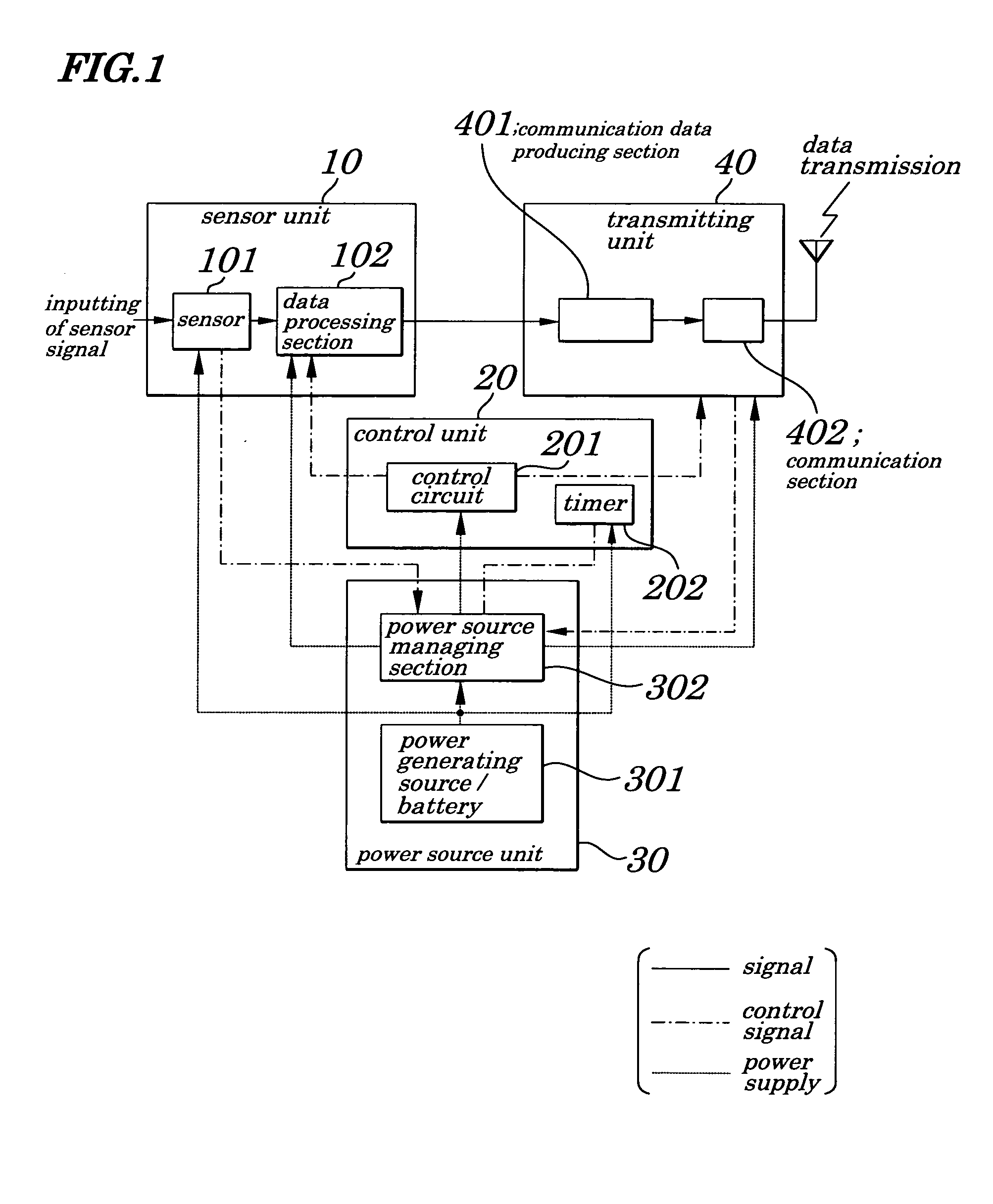
[0044]FIG. 1 is a configuration of a monitoring terminal device according to a first embodiment of the present invention. As shown in FIG. 1, the monitoring terminal device of the embodiment includes a sensor unit 10 to observe and monitor a specified kind of physical quantity, a control unit 20, a power source unit 30, and a transmitting unit 40.

[0045]The sensor unit 10, which converts a physical quantity such as a temperature into an electrical signal, is made up of a sensor 101 used to output a starting signal to a power source managing section 302 by detecting a state change (a temperature change or a like) of an object to be monitored (measured). In the connection with measurement of temperatures, there is a bimetallic thermometer, as one example of the sensor 101, and more, a proximity perception sensor using a lead switch (a opening or closing window sensor or a like), a mercury switch for detecting slope to be used for detecting tumble of a kerosene heater, and a thermistor ...

second embodiment

[0061]FIG. 6 is a block diagram of a monitoring terminal device of a second embodiment of the present invention. In FIG. 6, same reference numbers are assigned to components having the same function as those in FIG. 1. In the second embodiment a delay circuit 203 is added to decide operation time of a control circuit 201, a data processing section 102, and a transmitting unit 40 other than the components shown in FIG. 1. The control circuit 201, which is started with power supply from a power source managing section 302, operates the data processing section 102 and the transmitting unit 40 during a specific period of time. The specific period of time is decided by a time constant of the delay circuit 203, which is also started with power supply from the power source managing section 302. As a matter of course data transmission must be reached completion within the above specific period of time.

[0062]A mono stable multi vibrator (MMV) or a counter can be used as one example of the de...

third embodiment

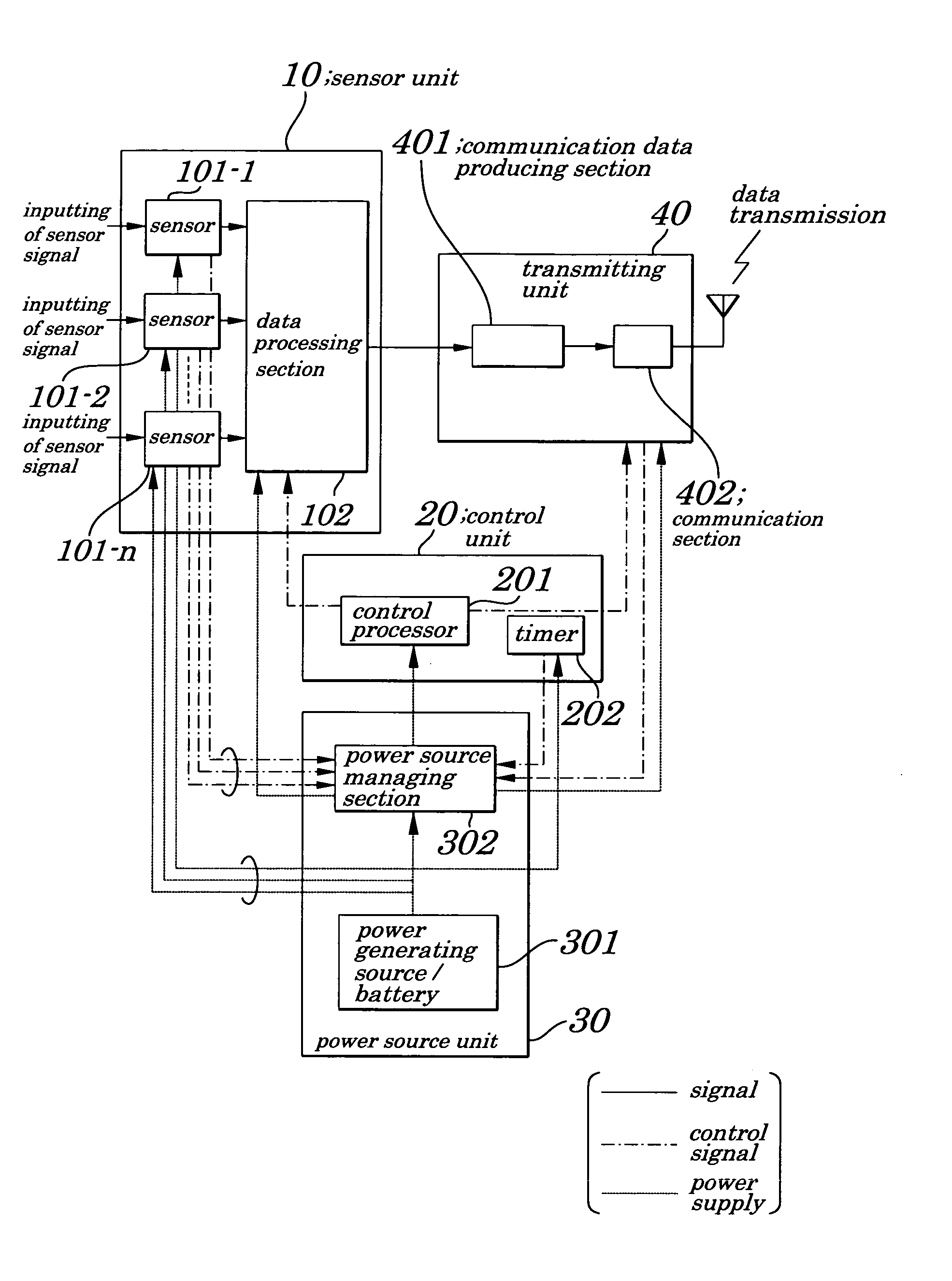
[0063]FIG. 7 is a block diagram of a monitoring terminal device according to a third embodiment of the present invention. In FIG. 7, same reference numbers are assigned to components having the same function as those in FIGS. 1 and 2. Referring to FIG. 7, a sensor unit 10 has two or more sensors 101-1 to 101-n (“n” is an integer being 2 or more), each of which monitors and measures a different physical quantity, and its data is transmitted from a transmitting unit 40. In the third embodiment, as an example of each of the sensors 101-1 to 101-n, a bimetallic thermometer for measurement of temperatures, a proximity perception sensor (lead switch) for detection of a closing or opening state of a window, or a mercury switch for detecting slope to be used for detecting tumble. Moreover, any sensor, so long as can start a power source managing section 302 with detecting state change (temperature change or a like) of object to be measured is not limited to sensors mentioned above. FIG. 8 i...


PUM


Abstract

A monitoring terminal device is provided which is capable of reducing its power consumption to a minimum and of being fully operated even indoors by using a solar cell as a power source. In the monitoring terminal device including a sensor unit, the transmitting unit to transmit, by wireless, a sensor monitoring output, and a control unit which control the sensor unit and the transmitting unit, further including a power supply section, when only state change of object to be monitored, that is, a output of the sensor unit is detected the control unit and the transmitting unit are started to transmit monitoring information by the sensor unit. When the sensor unit and the generating section are not activated supply of power to the sensor unit and the generating section is stopped and the control unit by itself is put into standby state, which enables reduction of power consumption to a minimum. This ensures a operation of the monitoring terminal device even in an environment in which power is not supplied from the outside.

Description

BACKGROUND OF THE INVENTION[0001]1. Field of the Invention[0002]The present invention relates to a monitoring terminal device and more particularly to the monitoring terminal device having a sensor and a wireless communication unit to transmit, by wireless, a monitoring output fed from the sensor.[0003]The present application claims priority of Japanese Patent Application No. 2003-150062 filed on May 28, 2003, which is hereby incorporated by reference.[0004]2. Description of the Related Art[0005]Applications of communications terminals in a communication network typified by the Internet are spreading out from a personal computer and / or a portable cellular phone to an information household electrical appliance. Moreover, by placing various sensors that can observe and monitor a variety of physical quantities in every location where needed in an artificial environment and / or a natural environment and by using information fed from these sensors, it is anticipated that the artificial en...

Claims


Application Information

Patent Timeline
IPC IPC(8): G08B1/08G08C17/00G08B13/00G08B17/00G08B21/00G08B23/00G08B25/10G08B29/12H04B1/04
CPCG08B13/00G08B15/004G08B17/00G08B29/12G08B23/00G08B25/007G08B25/10G08B21/00
Inventor KOBAYASHI, IKUTARO
Owner NEC CORP
Why Eureka
Try Eureka