Selective potting for controlled failure and electronic devices employing the same

a technology of electronic devices and selective potting, which is applied in the direction of electric variable regulation, process and machine control, instruments, etc., can solve the problems of unencapsulated controllers, electrical faults are more likely to occur in unencapsulated controllers, and the protected system is disabled, so as to reduce the likelihood of failure that causes damage or an undesired (or dangerous) condition

Inactive Publication Date: 2007-03-06
MEDTRONIC MIMIMED INC
View PDF12 Cites 104 Cited by
  • Summary
  • Abstract
  • Description
  • Claims
  • Application Information

AI Technical Summary

Benefits of technology

[0010]It is an object of embodiments of the present invention to provide a system and method of selectively protecting electrical and/or electronic components or circuits within a

Problems solved by technology

Thus, the failure of the non-critical components may disable the protected system in the event that the system becomes contaminated.
Accordingly, the system may be disabled before the critical electrical and electronic components and/or circuits can be contacted by the contaminant, which could then fail in a ma

Method used


Image

  • Selective potting for controlled failure and electronic devices employing the same
  • Selective potting for controlled failure and electronic devices employing the same
  • Selective potting for controlled failure and electronic devices employing the same

Examples


first embodiment

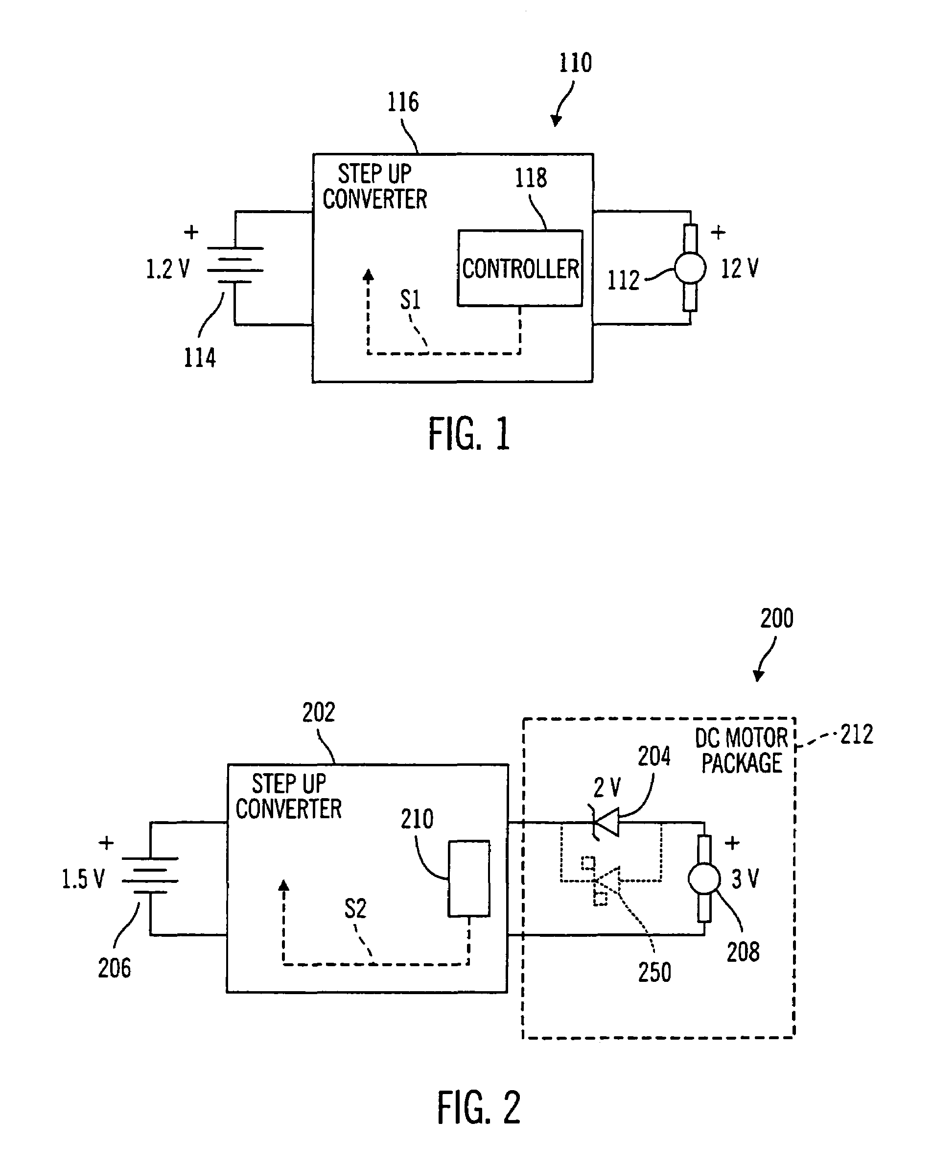
[0056]FIG. 1 illustrates a safety circuit 110 in accordance with the present invention. In this embodiment, a DC motor 112 is configured to have a nominal voltage winding that is significantly higher then a supply voltage from a battery 114. To generate a sufficient voltage to operate the DC motor 112, the safety circuit 110 utilizes a DC-DC step up converter 116 (or similar), that includes an integral controller 118, between the battery 114 and the DC motor 112 to drive the DC motor 112 at its rated voltage (see FIG. 1). Generally, when a DC motor is supplied with the rated voltage (and also assuming there is sufficient current available), the DC motor will provide a known torque. If, for example, the supply voltage is halved, then the DC motor will only provide approximately half the full voltage output torque. However, a two, or more, times DC-DC step up converter could be utilized between the battery and the DC motor to provide the rated voltage to the DC motor. Thus, to provide...

second embodiment

[0059]FIG. 2 illustrates a safety circuit 200 in accordance with the present invention that builds upon the embodiment shown in FIG. 1. The safety circuit 200 utilizes a DC-DC step up converter 202 (that includes integral control electronics 210) and a Zener diode 204. The DC-DC step up converter 202 converts the supply voltage from the battery 206 to a value corresponding to the sum of the rated motor winding voltage of the DC motor 208 and the Zener diode 204. For instance, if the DC motor 208 has 3.0 volt motor winding and the Zener diode 204 has a breakdown voltage of 2.0 volts, the DC-DC step up converter 202 must provide 5.0 volts to facilitate operation of the DC motor 208 at its nominal rated voltage, if it is desired to drive the DC motor 208 at the rated voltage. Thus, in this example, when the supply voltage from the battery 206 is stepped up to 5 volts as a positive voltage potential, 2 volts are lost through the Zener diode 204 and 3 volts are provided for operation of ...

third embodiment

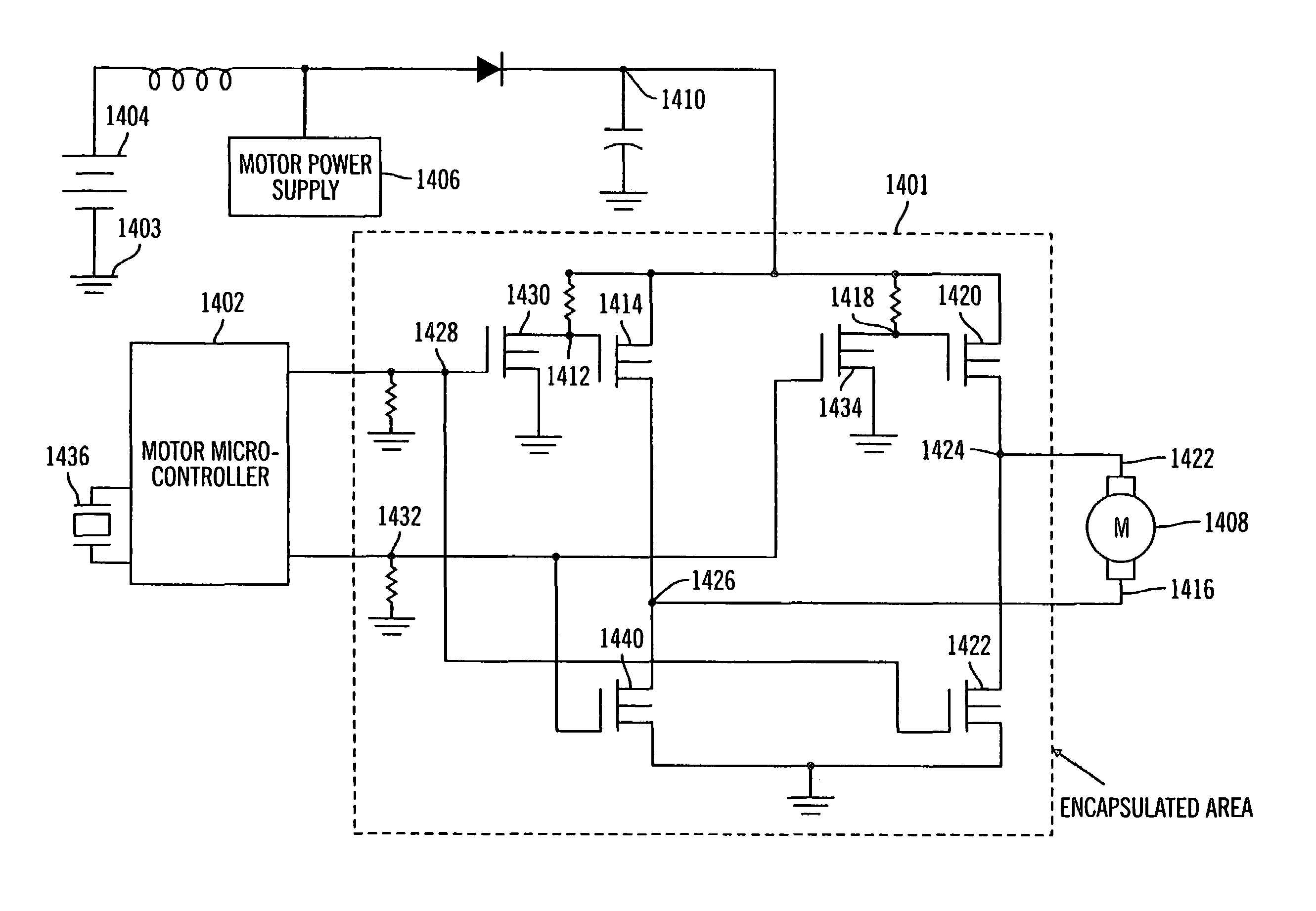
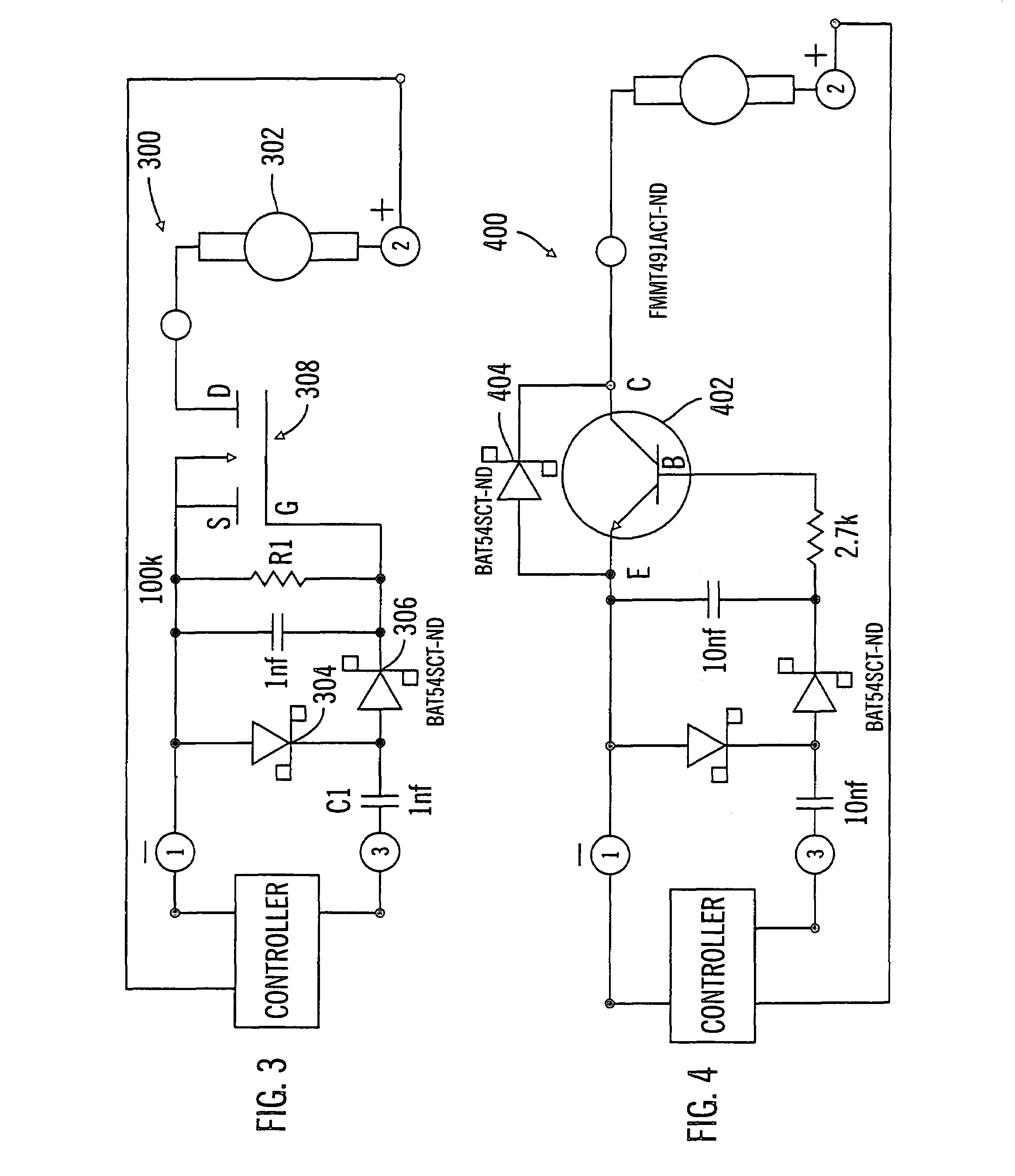
[0062]FIG. 3 illustrates a safety circuit 300 in accordance with the present invention, which includes further enhancements to provide protection against DC motor 302“run away”. The safety circuit 300 includes additional electronics added to the DC motor package (as shown in FIG. 7) that are independent of the control electronics. Alternatively, the additional electronics may be included in the control electronics (as shown in FIG. 8) or as a separate set of control electronics (not shown). In preferred embodiments, the control electronics must provide a specific signal (at terminal 3) to the additional electronics to allow the DC motor 302 to operate. As shown in FIG. 3, the rated supply voltage from the battery (not shown) is supplied to terminals 1 and 2 as a negative and positive voltage potential, respectively, to control operation of the DC motor 302 in the forward direction. However, current will not pass through the DC motor 302 until a specific AC signal (e.g., a 3 volt Pea...


PUM


Abstract

A selectively protected electrical system includes or operates with a power source, a load, a power driver circuit for controllably transferring power from the power source to the load, the power driver circuit being encapsulated in a potting material, and a controller for enabling and disabling the power driver circuit, the controller being un-encapsulated by the potting material. If a contaminant induced electrical fault occurs in the selectively protected electrical system, the electrical fault is more likely to occur in the un-encapsulated controller, such that the selectively protected electrical system is disabled. The contaminant is inhibited from contacting and inducing an electrical fault in the power driver circuit, thus providing for a controlled failure of the selectively protected electrical system.

Description

RELATED APPLICATIONS[0001]The present disclosure is a divisional of U.S. patent application Ser. No. 10 / 013,943 filed Dec. 8, 2001 now U.S. Pat. No. 6,801,420 entitled SELECTIVE POTTING FOR CONTROLLED FAILURE AND ELECTRONIC DEVICES EMPLOYING THE SAME which is a Continuation in Part of U.S. patent application Ser. No. 09 / 838,699 filed Apr. 19, 2001 now abandoned entitled, DIRECT CURRENT MOTOR SAFETY CIRCUITS FOR FLUID DELIVERY SYSTEMS (now abandoned), which is incorporated herein by reference.FIELD OF THE INVENTION[0002]This invention relates to a system and method for controlled failure in electronic devices and, in particular embodiments, to selective potting for controlling failures in defined operations such as controlled failure of a pump driver for delivery of medication or drugs to a patient.BACKGROUND OF THE INVENTION[0003]There are many types of electronic devices (medical devices, sensing devices, and the like) that can fail due to moisture or other environmental contaminan...

Claims


Application Information

Patent Timeline
IPC IPC(8): H02H7/00G05F1/10A61M5/142B60R1/12H02J7/00H02M1/00H02M3/00H02M7/00H02P7/06H04M1/02H04M1/27H04M1/60H04M1/725
CPCA61M5/142H02M7/003H02J7/0042H02M3/00B60R1/12A61M2205/16A61M2205/17A61M2205/18B60R2001/1284H02M1/32H02J2310/23
Inventor TALBOT, CARY D.MOBERG, SHELDON B.CAUSEY, III, JAMES D.YONEMOTO, JAY A.
Owner MEDTRONIC MIMIMED INC
Why Eureka
Try Eureka