
Transition-time control in a high-speed data transmitter

a high-speed data and transmission time technology, applied in the field of transmission time control in high-speed data transmitters, can solve the problems of large variation in transmission time, small window of legal transition time, severe inter-symbol interference, etc., and achieve the effect of the highest possible speed of operation

Inactive Publication Date: 2007-03-06
FINISAR +1
View PDF27 Cites 16 Cited by
  • Summary
  • Abstract
  • Description
  • Claims
  • Application Information

AI Technical Summary

Benefits of technology

[0010]Prior art transition control systems controlled the transition time to be a fixed value, regardless of the bit time of the system. With a fixed transition time, a signaling system operating at a lower speed is forced to use a transition time optimized for the highest possible speed of operation, unduly stressing the bandwidth of the transmission medium.
[0011]In accordance with another aspect of the invention, transition time control controls the transition time of a controlled data signal to be proportional to bit time of a bit clock.

Problems solved by technology

In other applications, however, the window of legal transition times is small and such a large variation in transition time is unacceptable.
As explained in Dally and Poulton, pp 533–536, slowing the transition time of the pre-driver in this manner can lead to severe inter-symbol interference, especially at high signaling rates.
Often the pre-driver is so slow that it is not able to swing full-rail before the end of the bit time leading to significant inter-symbol interference due to the retained state.
Because the entire transition must occur in just one (or at most two) taps of the delay line, it is not possible to smoothly sequence the transition by using a tapped delay line to sequence transmitter segments.
This is because a faster transition time would stress the bandwidth of the transmission medium (package, PC board, and connectors) without offering any substantial advantage.
With such a ratio of transition time to bit time, it is not possible to control the transition time by slowing the predriver.
To do so would require the predriver to have a delay much longer than the bit time and thus would cause intersymbol interference.
Because of these limitations, prior-art high-speed signaling systems have not employed transition time control and, as a result, have incurred large variations in transition time across process, voltage, and temperature corners.

Method used

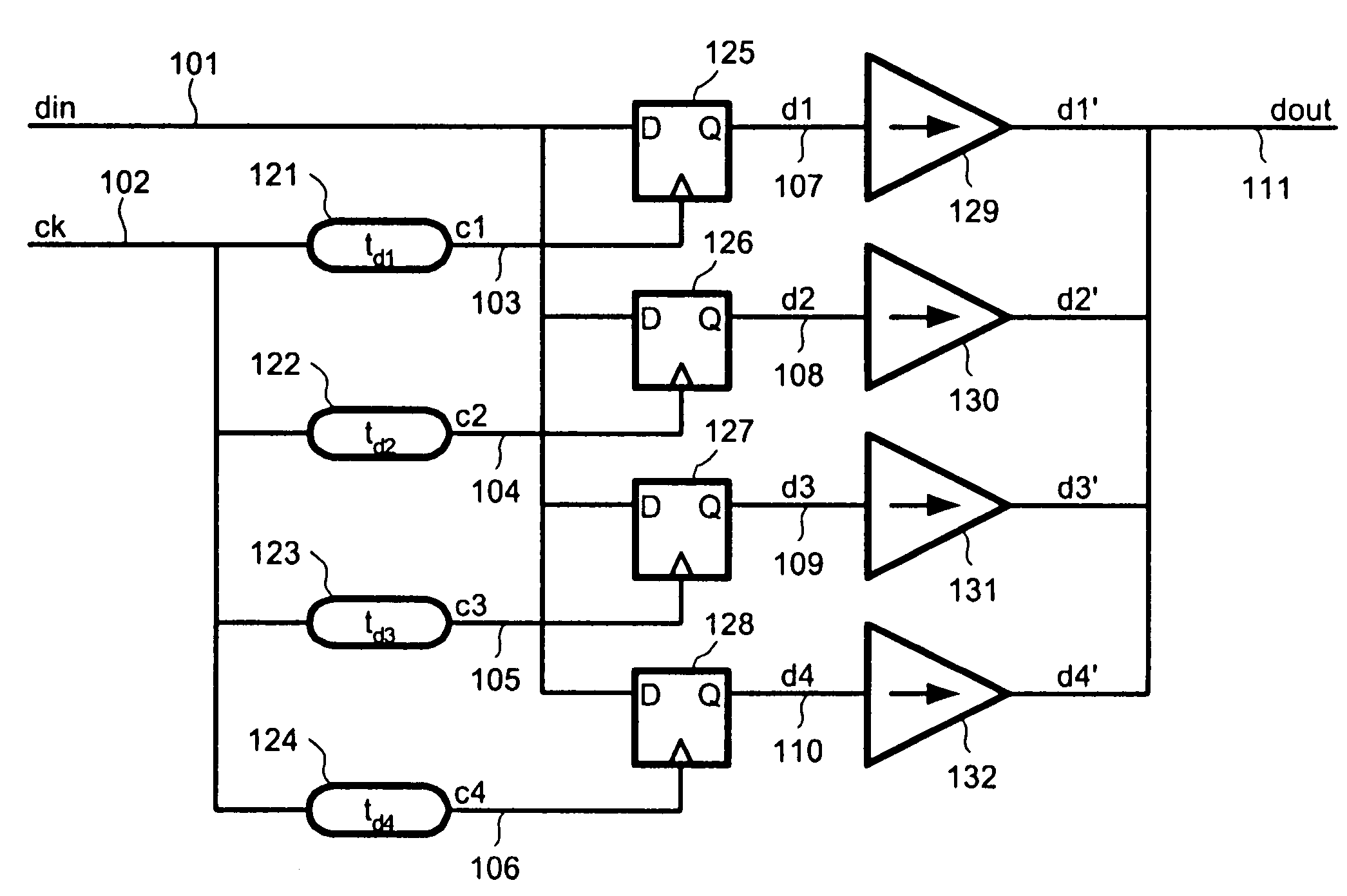

Image

  • Transition-time control in a high-speed data transmitter
  • Transition-time control in a high-speed data transmitter
  • Transition-time control in a high-speed data transmitter

Examples


Embodiment Construction

[0023]A description of preferred embodiments of the invention follows.

[0024]In a high-speed transmission system, where the bit time is less than 4 gate delays, prior art approaches to controlling rise time do not apply. A tapped delay line cannot be used since the desired transition time is comparable to the delay of a single tap. Slowing the predriver is also not appropriate as it will result in considerable ISI as the slow predriver stage will not reach a steady state before the end of each bit cycle.

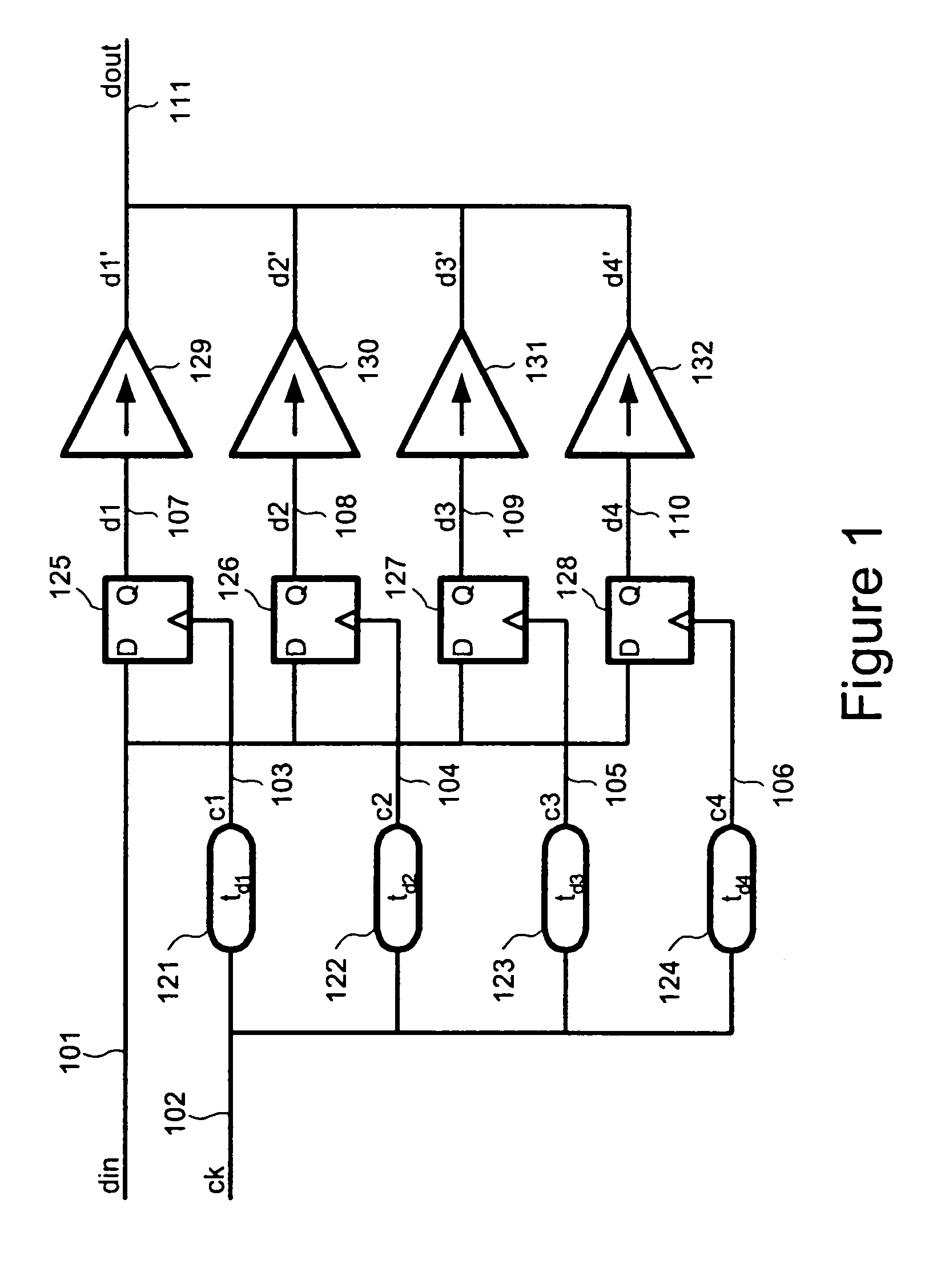
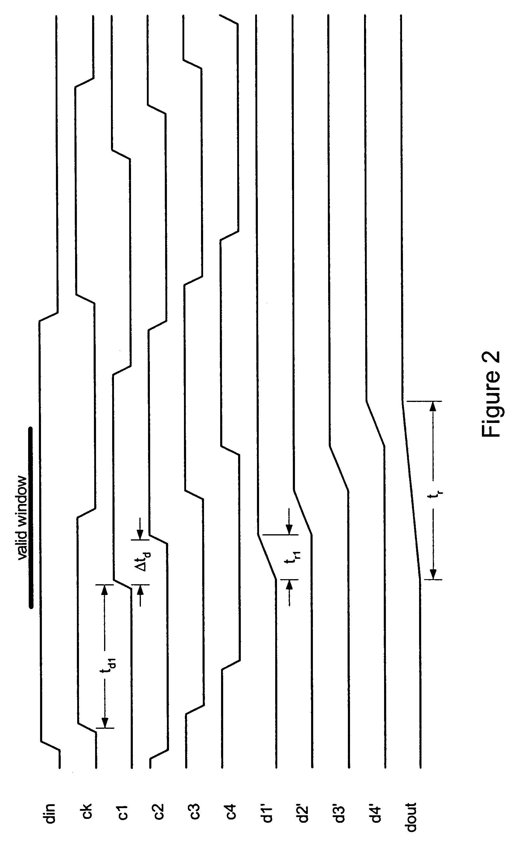
[0025]The present invention overcomes these limitations and controls the rise time of a high-speed transmitter by segmenting the transmitter and driving each segment with a variable delay element driven from a common clock node. By appropriately adjusting the delays of the variable delay elements the segment switching times can be set at intervals that are a small fraction of a gate delay resulting in a controlled transition time comparable to a single gate delay. With this approach t...


PUM


Abstract

Transition time of a data signal is controlled by applying different delays to the data signal and combining the delayed data signals. The transition time of the data output is determined by difference in delays applied to the data input and may be proportional to bit time of the bit clock. The data input may be applied directly to the delay elements or may be clocked by clock signals delayed by the delay elements. The delayed data is applied to parallel driver circuits. Supply voltage to the delay elements can be controlled to compensate for production and environmental variations. The supply voltage controller includes parallel delay elements of different delays and a phase comparator, the output of which controls the supply voltage applied to the delay elements.

Description

RELATED APPLICATION(S)[0001]This application claims the benefit of U.S. Provisional Application No. 60 / 181,276, filed Feb. 9, 2000, the entire teachings of which are incorporated herein be reference.BACKGROUND OF THE INVENTION[0002]The transition time, rise time or fall time, of an output driver is the time required for the output signal to slew between two voltages, typically 20% and 80% of full swing. In certain prior-art systems, for example, transition time must be maintained larger than a specified minimum value to keep the derivative of the supply current, and hence the inductive switching noise (sometimes called simultaneous switching output (SSO) noise), within limits. At the same time, transition time must be kept smaller than a maximum value to avoid excessive delay of the signal.[0003]Across variations in process parameters, supply voltage, and temperature, transition time can vary by a considerable amount, often by a factor of two or more. In some applications, the sprea...

Claims


Application Information

Patent Timeline
Patent Type & Authority Patents(United States)
IPC IPC(8): H04L27/04
CPCH04L25/0282H04L25/028
Inventor DALLY, WILLIAM J.POULTON, JOHN W.
Owner FINISAR
Learn More