
Viterbi decoder

a technology of viterbi decoding and decoding frequency, applied in the field of signal processing, can solve the problems of vain increase in circuit scale, error in decoding, and disturbance of high processing speed of circuit, and achieve the effect of suppressing an increase in circuit scale and improving the performance of viterbi decoding

Inactive Publication Date: 2007-03-06
SOCIONEXT INC
View PDF12 Cites 11 Cited by
  • Summary
  • Abstract
  • Description
  • Claims
  • Application Information

AI Technical Summary

Benefits of technology

[0010]An object of the present invention is to improve the performance of a Viterbi decoder while suppressing an increase in the circuit scale.
[0012]According to the present invention, a majority decision is made by using output values of a part of the delay circuits in the path holding part at the final stage. Consequently, the circuit scale of the required majority decision circuit is sufficiently small and, moreover, the performance of Viterbi decoding can be improved. Therefore, the high-precision Viterbi decoder with a small circuit scale can be realized.

Problems solved by technology

In other words, when output values of the delay circuits of the path holding part 3n at the final stage are not the same value, it means that an error occurs in decoding.
However, a problem occurs such that the circuit scale increases vainly in order to realize improvement in performance of Viterbi decoding.
The circuit scale of the path storing circuit increases by the increased amount of the majority decision circuit and it also disturbs high processing speed of the circuit.

Method used


Image

  • Viterbi decoder
  • Viterbi decoder
  • Viterbi decoder

Examples


embodiment 1

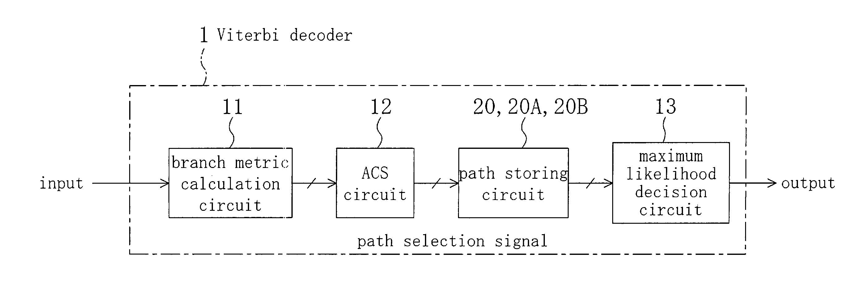
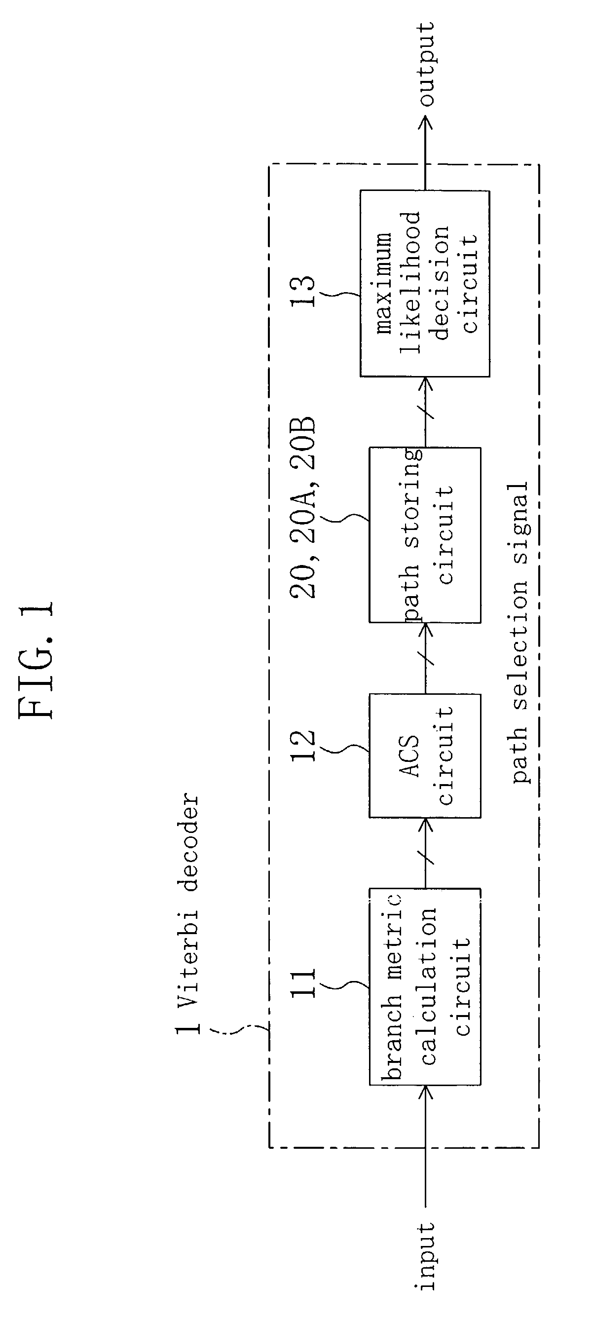
[0035]FIG. 1 is a block diagram showing the configuration of a Viterbi decoder according to a first embodiment. A Viterbi decoder 1 shown in FIG. 1 has a branch metric circuit 11, an add compare select (ACS) circuit 12, a path storing circuit 20, and a maximum likelihood decision circuit 13, and the configuration is similar to the conventional technique. The first embodiment is different from the conventional technique with respect to the internal configuration of the path storing circuit 20.

[0036]The branch metric circuit 11 calculates a branch metric which shifts from a certain state to another state in the trellis diagram, and the ACS circuit 12 performs addition, comparison, and selection of the minimum value (ACS computation) by using an output of the branch metric circuit 11 and outputs a path selection signal. The path storing circuit 20 stores the path selection signal output from the ACS circuit 12, thereby storing a path in the trellis diagram. Finally, the maximum likelih...

embodiment 2

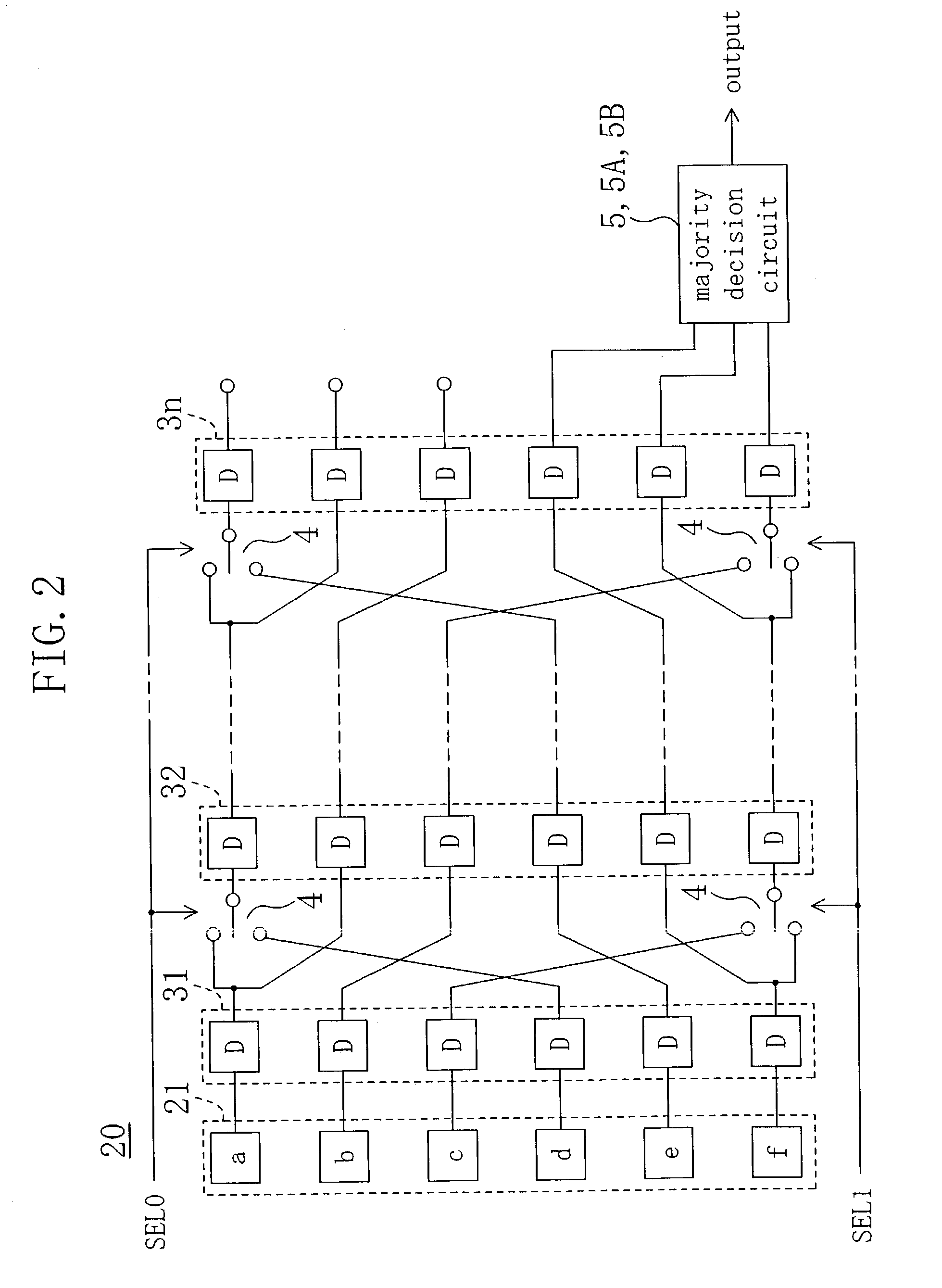
[0050]FIG. 7 is a diagram showing the internal configuration of a path storing circuit in a Viterbi decoder according to a second embodiment of the present invention. The configuration of FIG. 7 is different from that of FIG. 2 according to the first embodiment with respect to the point that the majority decision circuit 5 receives output values of three delay circuits including the top and bottom delay circuits to each of which the selector 4 is connected to the input side, out of delay circuits in the path holding part 3n at the final stage.

[0051]The input side of each of the delay circuits other than the top and bottom delay circuits (that is, the second to fifth delay circuits) in the path holding part 3n is not connected to the selector 4, but directly connected to an output of a delay circuit in another position in the path holding part at the immediately preceding stage. Consequently, even if output values of the second to fifth delay circuits are used for a decision by a maj...

embodiment 3

[0053]FIG. 8 is a diagram showing the internal configuration of a path storing circuit in a Viterbi decoder according to a third embodiment of the present invention. The configuration of FIG. 8 is different from that of FIG. 2 according to the first embodiment with respect to the point that a same signal decision circuit 15 for determining whether all of values input to the majority decision circuit 5 are the same or not is provided.

[0054]The same signal decision circuit 15 receives three values input to the majority decision circuit 5 and determines whether the three signals have the same value or not. When the same signal decision circuit 15 determines that the three signals are not the same, an error signal is output. By an output of the same signal decision circuit 15, the quality of a communication path or the quality of a recording / reproduction system characteristic can be checked. The performance of Viterbi decoding can be also checked. In the case where an error occurs, inte...


PUM


Abstract

A path storing circuit has path holding parts at a plurality of stages storing a survivor path and corresponding to times. A majority decision circuit receives output values of three delay circuits including the top and bottom delay circuits each receiving a selected output of a selector out of six delay circuits in the path holding part at the final stage and makes a decision by a majority.

Description

BACKGROUND OF THE INVENTION[0001]The present invention relates to a signal process of a reproducing unit in a communication system or a recording / reproducing apparatus and, more particularly, to a technique of Viterbi decoding used to decode a reproduction signal in a maximum likelihood manner.[0002]A Viterbi decoder is used to, for example, detect and correct an error in a signal subjected to waveform equalization at the time of reproducing a signal in a communication system or a recording / reproducing apparatus. By using waveform equalization and Viterbi decoding in a signal process, BER (Bit Error Rate) can be decreased.[0003]FIG. 9 is a diagram showing the internal configuration of a path storing circuit provided in a conventional Viterbi decoder. Shown in FIG. 9 are path selection signals SEL0 and SEL1, an initial value 21 of a path holding part, path holding parts 31, 32, . . . , and 3n for holding a survivor path, and selectors 4 for selecting a value to be input to the path h...

Claims


Application Information

Patent Timeline
IPC IPC(8): H03D1/00G06F11/10H03M13/23H03M13/41H03M13/43H04L1/00
CPCH03M13/41H03M13/6502H03M13/6331H03M13/43
Inventor NAGANO, KOUICHI
Owner SOCIONEXT INC
Learn More