Liquid discharge method and apparatus using individually controllable nozzles

a liquid crystal display device and individually controllable technology, applied in the field of liquid crystal display devices, can solve the problems of high cost, high cost, and increased demand for cost reduction

Inactive Publication Date: 2007-03-13
CANON KK
View PDF37 Cites 38 Cited by
  • Summary
  • Abstract
  • Description
  • Claims
  • Application Information

AI Technical Summary

Benefits of technology

[0031]The present invention has, therefore, been made in consideration of the above problems, and has as its object to control the amounts of liquid applied to predetermined areas (pixels) on a substrate to a predetermined amount so as to make the amounts of liquid applied to the predetermined areas (pixels) uniform while suppressing an increase in the circuit size of a liquid discharge amount control circuit (e.g., an ink discharge amount control circuit).

Problems solved by technology

However, liquid crystal display devices are expensive, and hence demand for cost reduction has increased year by year.
The above color filter manufacturing methods have a common feature that the same process must be repeated three times to color layers in three colors, i.e., R, G, and B, and hence the cost is high.
In addition, since a large number of processes are required, the yield decreases.
It is therefore difficult to discharge ink in an amount required for one pixel at once and uniformly spread the ink in the entire opening portion of the black matrix.
The variations in the amounts of ink filled lead to unevenness among the pixels, resulting in reductions in the quality and yield of color filters.
In a color filter in which no color mixing prevention wall is provided between color pixel arrays and only a BM (black matrix) is provided as a partition between pixels, unlike a color filter as described above which is colored in a stripe pattern with a color mixing prevention wall being provided between color pixel arrays, when ink is discharged in the form of a line on a pixel array basis, the ink discharged onto the water-repellent BM flows into an adjacent pixel area, resulting in difficulty in managing the amount of ink discharged into each pixel.
That is, it is difficult to control the amount of ink applied into a pixel to a predetermined amount by using a method of adjusting discharge intervals as in the above shading correction.
This makes it more difficult to control the amount of ink filled in each pixel.
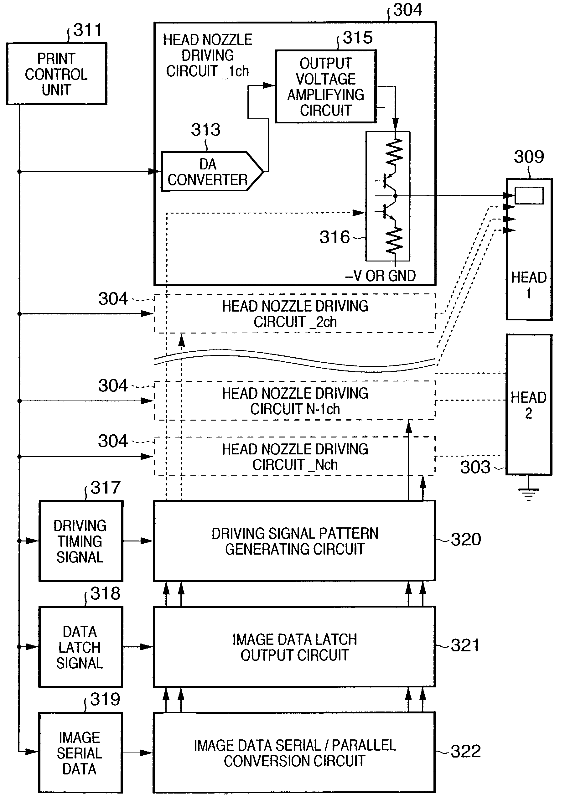
However, in the form in which the head nozzle driving circuits 304 are provided in number equal to the number of nozzles, as the number of nozzles increases, the number of head nozzle driving circuits 304 increases, resulting in increases in circuit size and cost.
This leads to increases in circuit size, cost, and control load.
This in turn poses a problem in terms of apparatus design, that is, a head nozzle control circuit is too large to be mounted.
Furthermore, an increase in overall apparatus size poses problems in terms of difficulty in handling, an increase in consumption power, and an increase in the cost of the apparatus.
However, the above problems arise not only in the manufacture of color filters but also in a case wherein the amount of liquid applied to a predetermined area (pixel) on a substrate must be controlled to a predetermined amount.
For example, such problems arise in a case wherein a predetermined amount of EL (electroluminescence) material liquid is applied from a liquid discharge head (ink-jet head) to a predetermined area on a substrate to manufacture an EL display device.
In addition, similar problems arise in a case wherein a predetermined amount of conductive thin film material liquid (liquid containing a metal element) is applied to a predetermined area on a substrate to manufacture an electron-emitting device obtained by forming a conductive thin film on a substrate or a display panel including a plurality of such devices.

Method used


Image

  • Liquid discharge method and apparatus using individually controllable nozzles
  • Liquid discharge method and apparatus using individually controllable nozzles
  • Liquid discharge method and apparatus using individually controllable nozzles

Examples


Embodiment Construction

[0082]A preferred embodiment of the present invention will be described below with reference to the accompanying drawings.

[0083]Note that a display device panel defined in the present invention is a panel used for a display device, including, for example, a display panel including a plurality of color filters having colored portions, EL devices having light-emitting portions formed of a spontaneous emission material (EL material), or electron-emitting devices having conductive thin film portions.

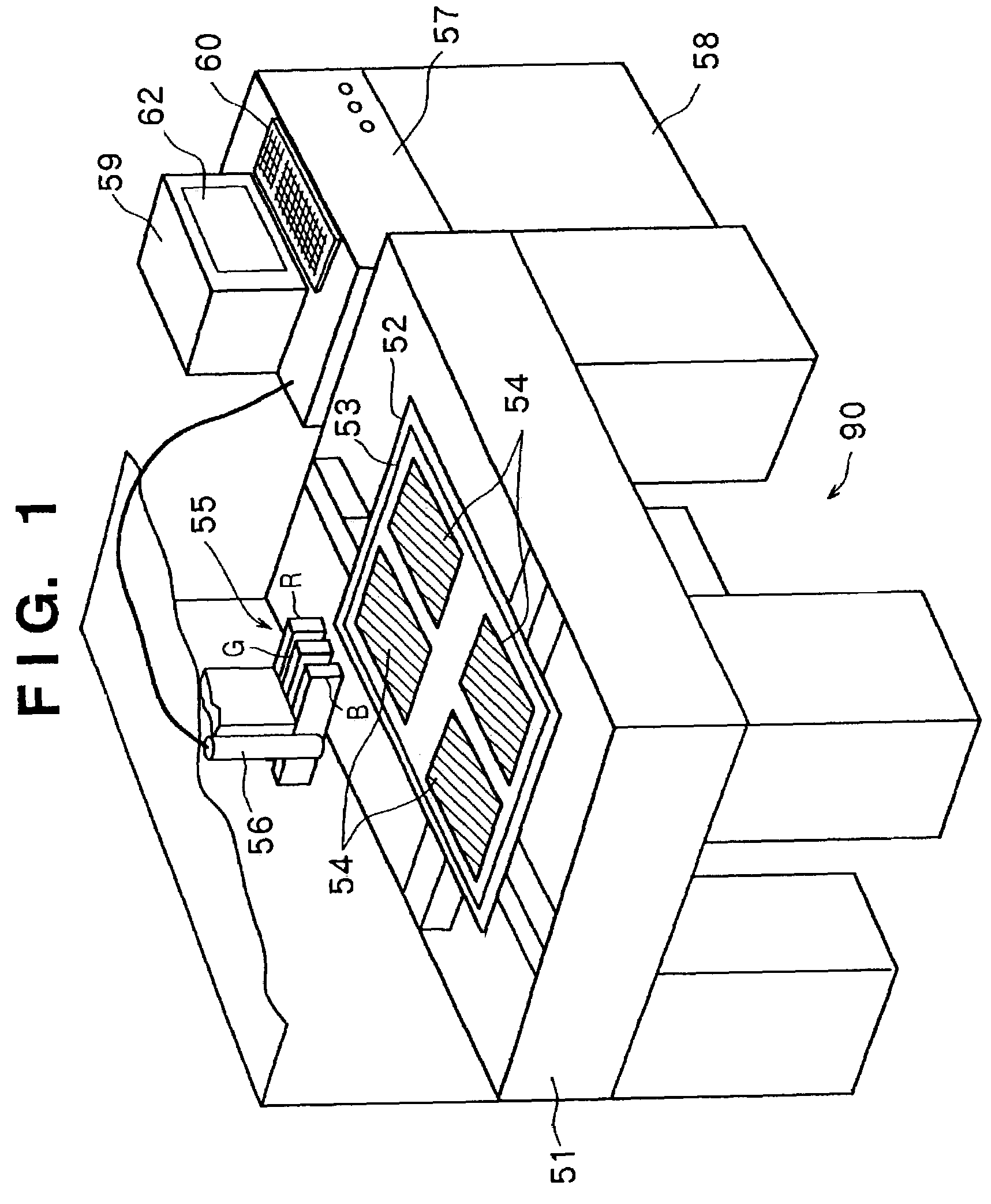
[0084]A color filter defined in the present invention is a filter comprised of colored portions and base members and capable of obtaining output light upon changing the characteristics of input light. More specifically, in a liquid crystal display device, backlight light is transmitted through such a color filter to obtain light of the three primary colors, i.e., R, G, and B or C, M, or Y, from the backlight light. Note that the base member in this case includes a substrate made of a glass o...


PUM

PropertyMeasurementUnit
thicknessaaaaaaaaaa
voltageaaaaaaaaaa
voltageaaaaaaaaaa

Abstract

The amounts of liquid discharged from a liquid discharge head to predetermined areas can be made uniform while suppressing an increase in circuit size. In order to achieve this object, there is provided a liquid discharge apparatus which discharges a liquid from a liquid discharge head having a plurality of nozzles for discharging the liquid, wherein the liquid discharge head includes a subset of nozzles capable of individually controlling liquid discharge amounts, among the plurality of nozzles. The subset of nozzles is smaller in number than the total number of the plurality of nozzles.

Description

FIELD OF THE INVENTION[0001]The present invention relates to a technique of printing a predetermined pattern by using a liquid discharge head (e.g., an ink-jet head).BACKGROUND OF THE INVENTION[0002]In general, liquid crystal display devices are mounted in personal computers, wordprocessors, pachinko machines, vehicle navigation systems, small-size TV sets, and the like, and have recently been in increasing demand. However, liquid crystal display devices are expensive, and hence demand for cost reduction has increased year by year. Of the components of a liquid crystal display device, a color filter exhibits a high cost ratio, and demand for a reduction in the cost of the color filter has increased.[0003]A color filter used in a liquid crystal display device is formed by arraying filter elements colored in, for example, red (R), green (G), and blue (B) on a transparent substrate. A black matrix (BM) for blocking light is provided around each filter element to improve the display con...

Claims


Application Information

Patent Timeline
Patent Type & Authority Patents(United States)
IPC IPC(8): B41J29/38B05C5/00B05D5/06G02F1/13B41J2/05
CPCB41J2/04506B41J2/04528B41J2/0458B41J2/04588B41J2/04591B41J2/04593B41J2/04596B41J2/04598B41J2/0459B41J2202/09G02F1/13
Inventor SATOMURA, SEIICHIROU
Owner CANON KK
Why Eureka
Try Eureka