Preformed pavement warning assembly and method

a warning assembly and preformed technology, applied in the field of pavement warning assemblies, can solve the problems of difficult retrofitting to contoured curb ramps, difficult to precisely timing, rigid assembly, etc., and achieve the effect of reducing the difficulty of detection of warning assemblies, and reducing the difficulty of detection

Active Publication Date: 2007-03-13
ENNIS FLINT INC
View PDF36 Cites 56 Cited by
  • Summary
  • Abstract
  • Description
  • Claims
  • Application Information

AI Technical Summary

Benefits of technology

[0062]Heating of the primer on the base surface or substrate if required (such as the sidewalk) and pavement warning assembly may be accomplished by a Flint 2000EX heat gun, manufactured by Flint Trading, Inc. of Thomasville, N.C. Standard open flame, closed flame, heated rollers, electrically resistive heaters or other conventional heaters may also be used. The application of cool water such as by pouring or spraying after heating will hasten solidification, strengthening and curing of the pavement warning assembly.

Problems solved by technology

Many of these assemblies are rigid and difficult to retrofit to contoured curb ramps.
In the so-called two-step process, a separate adhesive layer and warning layer are composed of different materials and applied to a substrate at different times. One deficiency of such process is that after heating the adhesive layer on the substrate precise timing is required for placing the detectable warning device on the molten adhesive.
If too much time is taken allowing the adhesive to cool an insufficient bond is established between the detectable warning device and the adhesive layer.
The surface properties therefore represent a considerable challenge for attachment of the detectable warning assemblies.
Thus the thermoplastic warning assembly requires greater curing time for permanent application thereby leaving the traffic area non-ADA compliant until the concrete is completely cured.
Such residuals are cleaned from the concrete surface via grinding or high pressure washing, leaving the concrete surface wet.
While prior single layer pavement warning devices are useful in certain circumstances, a single layer warning device does not allow easy variation in the type, size or height of the projections.
Further, a single layer warning device is more difficult to properly adhere to the rigid base substrate if the substrate is irregular, uneven or not level.

Method used


Image

  • Preformed pavement warning assembly and method
  • Preformed pavement warning assembly and method
  • Preformed pavement warning assembly and method

Examples


Embodiment Construction

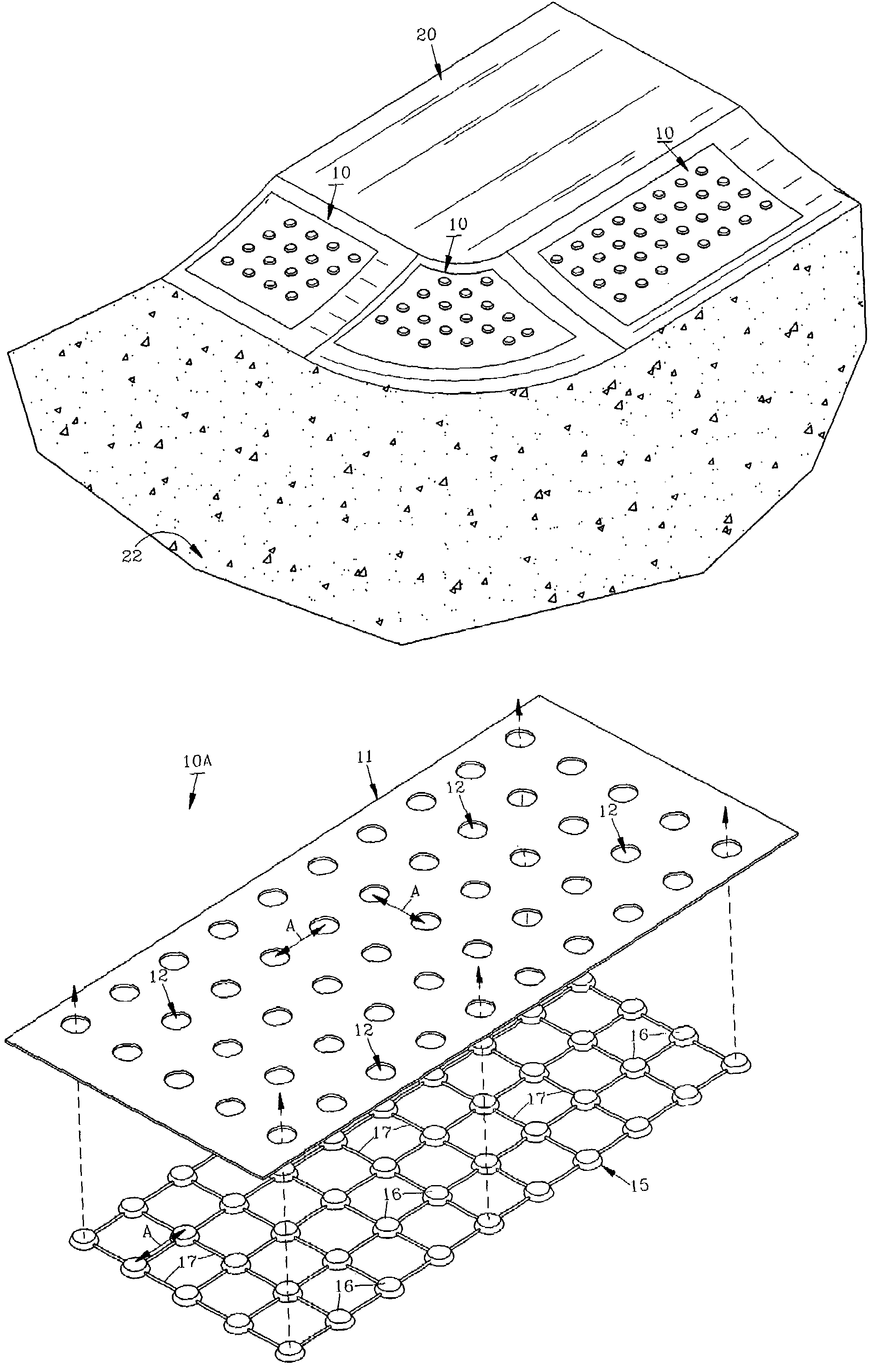
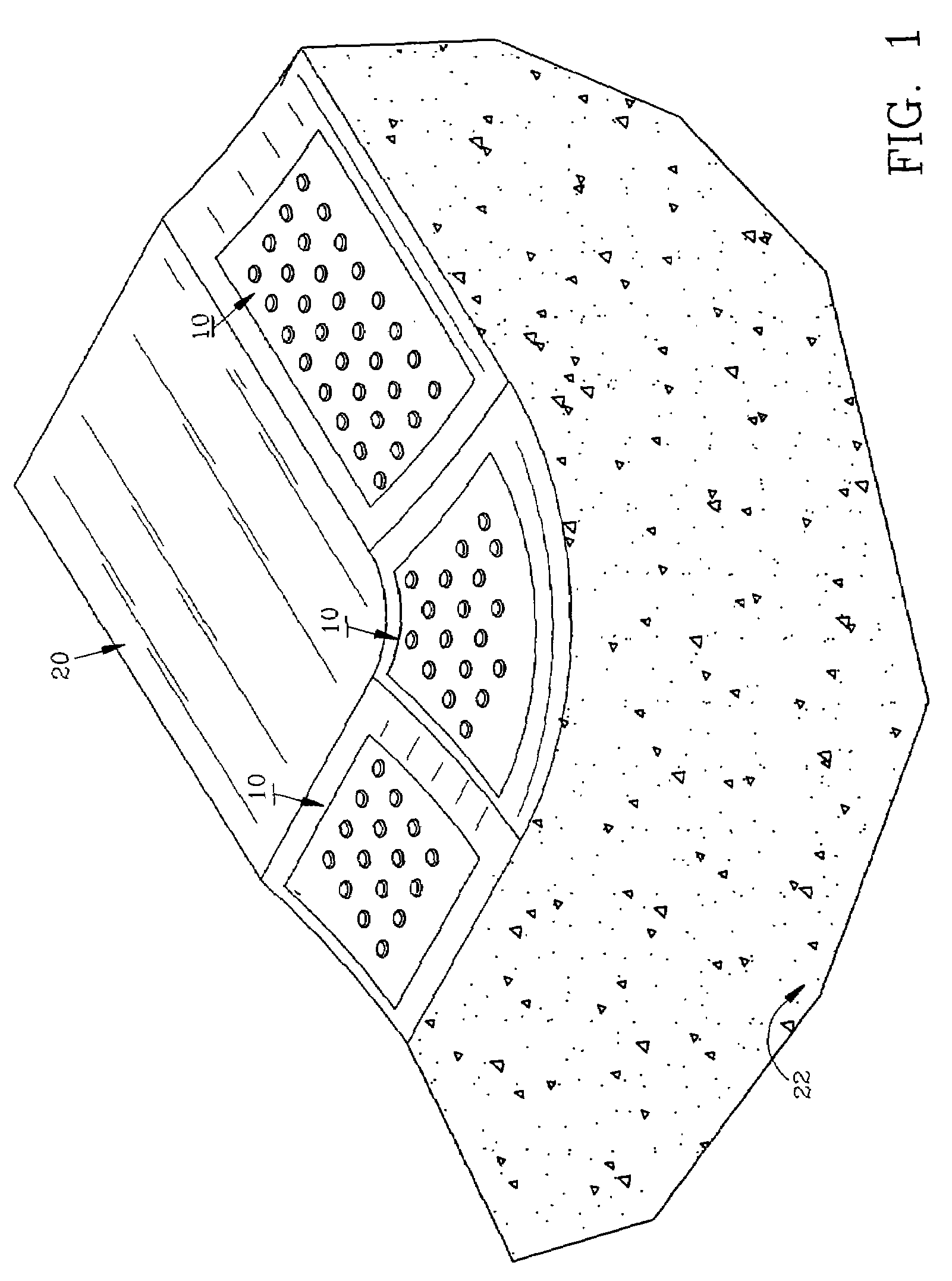
[0068]For a better understanding of the invention and its method of application to a substrate, turning now to the drawings, FIG. 1 schematically illustrates a typical fragmented sidewalk section 20 as formed from concrete with a height of approximately four (4) inches (10.2 cm) which slopingly abuts roadway 22 at a typical corner or intersection. Preferred detectable pavement warning assemblies 10 are shown positioned in three (3) locations to provide tactile warnings to pedestrians, such as visually impaired pedestrians as they walk across warning assemblies 10 to roadway 22. One or more pavement warning assemblies 10 may be utilized in a typical installation.

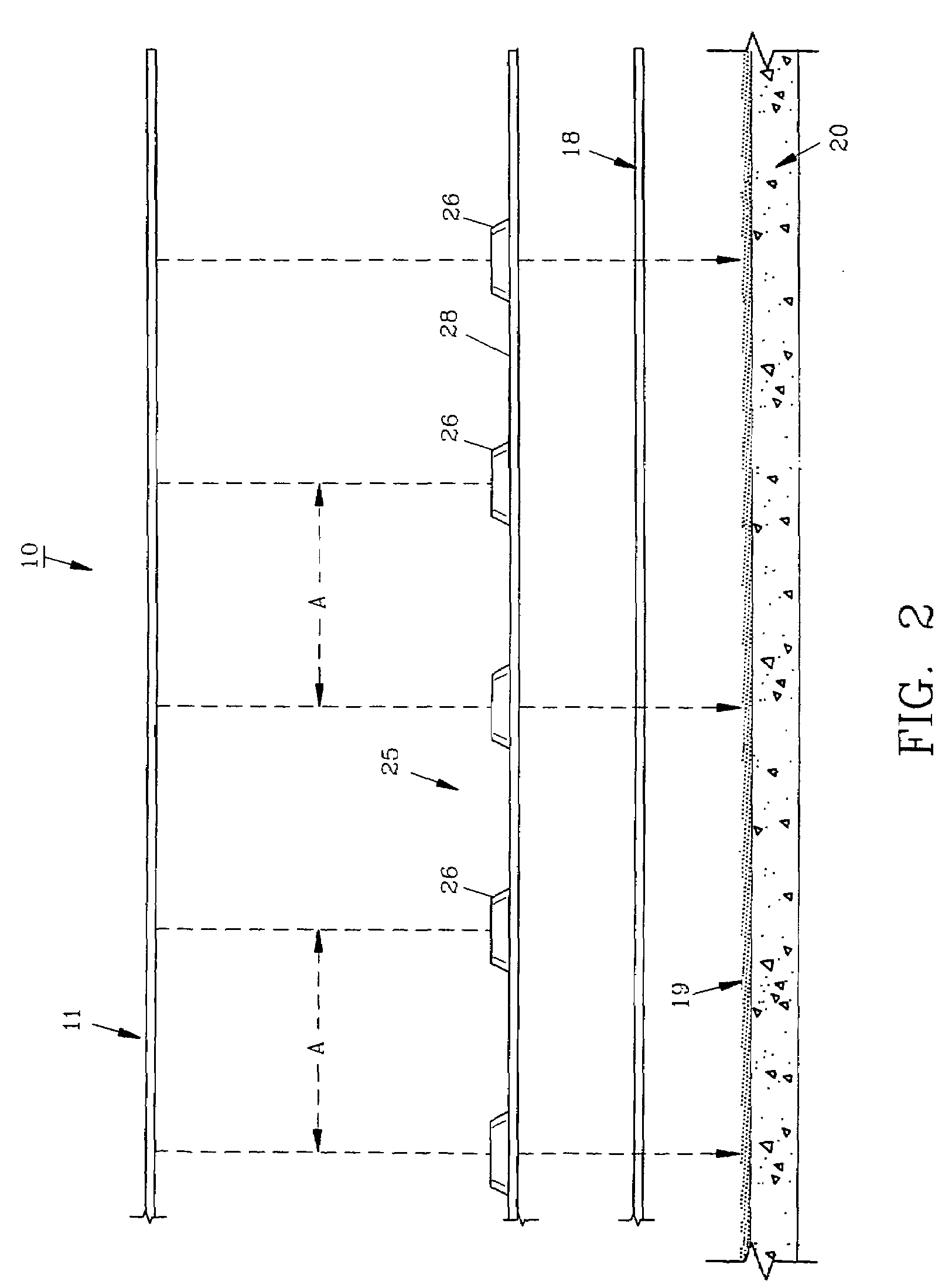
[0069]Preferred pavement warning assembly 10 includes planar top layer or cover 11, web 25 and bottom adhesive layer 18 as seen exploded in FIG. 2 prior to assembly and installation on sidewalk section 20 having a standard polyurea-epoxy primer 19 thereon. Cover 11 is formed by conventional stamping of a planar thermoplastic,...


PUM

PropertyMeasurementUnit
bond strengthaaaaaaaaaa

Abstract

A detectable pavement warning assembly includes a web having a plurality of projections attached to one another by linear connectors, a planar cover with a series of apertures for receiving the projections therethrough and an adhesive sheet. In use a rigid substrate such as a sidewalk is selected, and a primer is applied. The web, cover and adhesive sheet all pre-assembled are placed on the primed substrate. Next, the warning assembly is heated with an open flame to soften and fuse the pavement warning assembly with the primed substrate. The projections will remain extended sufficiently above the cover to provide a warning to pedestrians that walk thereon, such as when approaching a traffic area or other hazard.

Description

FIELD OF THE INVENTION[0001]The invention herein pertains to pavement markers and particularly pertains to a multi-layer detectable pavement warning assembly, method of application and primer composition for adhering the pavement warning assembly to a rigid substrate to inform visually impaired pedestrians that they are approaching a dangerous traffic pattern.DESCRIPTION OF THE PRIOR ART AND OBJECTIVES OF THE INVENTION[0002]Various types of warning assemblies and the like have been used over the years to warn pedestrians of approaching hazards such as curbs or crosswalks when walking along sidewalks or walkways. Usual pavement markings convey information to pedestrians by providing exposed visible, reflective and / or tactile indicia upon a traffic or walking substrate. In the past such a function was typically accomplished by painting a substrate, but this could not be seen by visually impaired individuals. In more recent years polymeric sheets have been formed with small raised dome...

Claims


Application Information

Patent Timeline
Patent Type & Authority Patents(United States)
IPC IPC(8): E01C11/24
CPCE01C11/222E01C5/20A61H3/066
Inventor GREER, ROBERT W.CORBETT, CHRISTOPHER J.
Owner ENNIS FLINT INC
Why Eureka
Try Eureka