
Molecular electronics arrangement and method for producing a molecular electronics arrangement

a technology molecular electronics, applied in thermoelectric devices, instruments, nanoinformatics, etc., can solve the problems of reducing the number of transistors per chip, affecting the development efficiency of molecular electronic molecules, and affecting the ability to bind molecular electronic molecules, so as to reduce the amount of investmen

Inactive Publication Date: 2007-03-13
POLARIS INNOVATIONS
View PDF9 Cites 7 Cited by
  • Summary
  • Abstract
  • Description
  • Claims
  • Application Information

AI Technical Summary

Benefits of technology

[0017]The invention is based on the problem of providing a molecular electronics arrangement in which molecular electronic molecules can be precisely coupled to electrodes with a reduced outlay, and in which the molecular electronic molecules are better protected against destruction.

Problems solved by technology

In particular the development of increasingly smaller and more densely arranged transistors of hundreds of millions of transistors per chip will be subject to fundamental physical problems in the next ten years.
The increasing integration density of the components on a chip also leads to a dramatic increase in the waste heat.
In this case, the problem arises that it is necessary to bind the molecular electronic molecules to suitable contacts, for example metallic conductors.
Even though this procedure is suitable for laboratory experiments, it is unsuitable for the integration of many molecular bridges.
Therefore, the method described is too time-consuming and too expensive to be considered for the mass production of arrangements with a large multiplicity of molecular electronic components.
Furthermore, the degree of reproducibility is low in the case of the described method for coupling metallic conductors by means of a molecular electronic molecule.
It is difficult to carry out the tearing-away of the constricted gold interconnect by the bending device under controlled conditions.
Furthermore, slightly different torn-away ends are obtained in each tearing-away operation, so that it is not possible to exactly set the distance between the torn-away ends.
Biomolecules are often unstable compounds which react extremely sensitively to excessively high temperatures.
For arrangements of economic interest, however, no consideration can be shown for the sensitivity of the molecules during the formation of the second electrode if the arrangements fabricated in accordance with the method are intended to be economically competitive.
On the other hand, consideration must be shown for the intactness of the biomolecules, since biomolecules are frequently present only in low concentrations and are often expensive.
Therefore, the method described is suitable only to a very limited extent for introducing sensitive, in particular temperature-sensitive, biomolecules.
Thus, structurally adequately defined arrangements cannot be fabricated in accordance with the known techniques and the methods are complicated, expensive and not suitable for economic mass production.

Method used


Image

  • Molecular electronics arrangement and method for producing a molecular electronics arrangement
  • Molecular electronics arrangement and method for producing a molecular electronics arrangement
  • Molecular electronics arrangement and method for producing a molecular electronics arrangement

Examples


Embodiment Construction

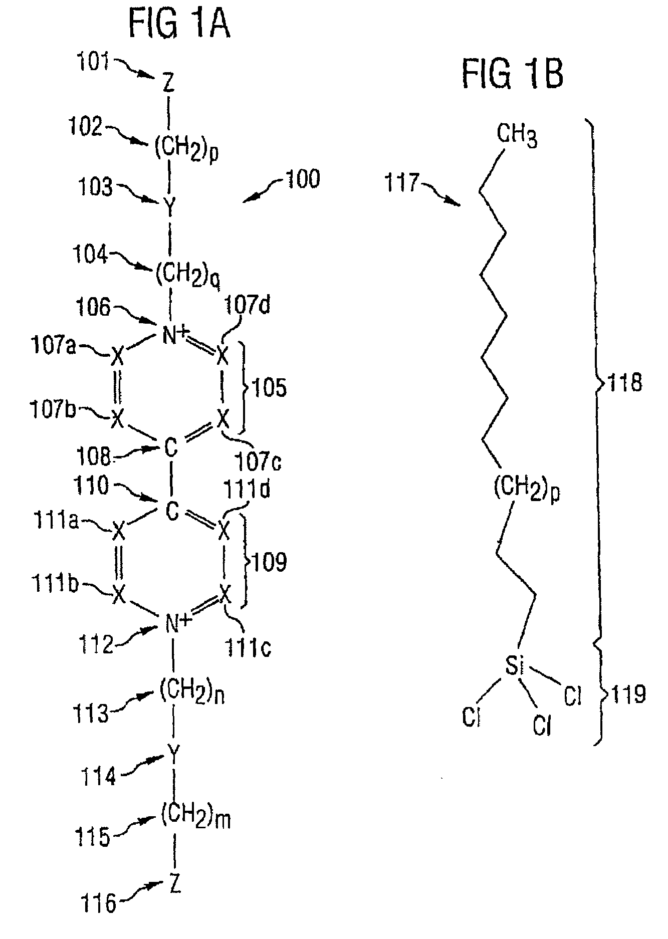
[0085]Firstly, a description is given, with reference to FIGS. 1A–1B, of exemplary embodiments of molecular electronic molecules as are included in the molecular electronics arrangement of the invention.

[0086]The structure of redox-active bispyridinium molecules 100 is described below with reference to FIG. 1A. As disclosed in [2], the electrical resistance of redox-active bispyridinium molecules 100 can be switched back and forth between two values, the electrical resistance being low in the reduced redox state and the electrical resistance being high in the oxidized redox state.

[0087]The redox-active bispyridinium molecule 100 shown in FIG. 1A has a few substituents (designated by X, Y, Z) which serve as spacers for a chemical element or a chemical group or for a molecule radical. Furthermore, variables p, q, n, m are shown in the bispyridinium molecule 100 shown in FIG. 1A, each of which variables assumes an integral positive value (1, 2, 3, . . . ) independently of one another.

[...


PUM


Abstract

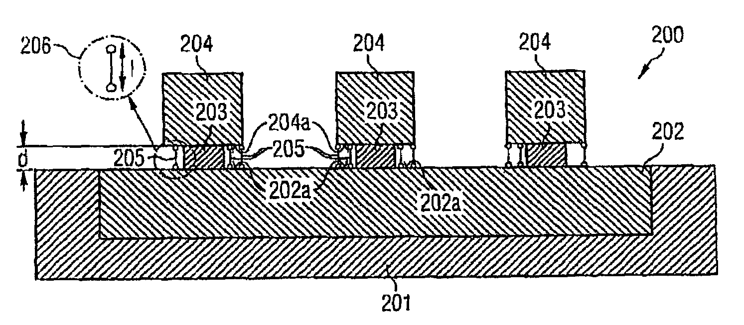
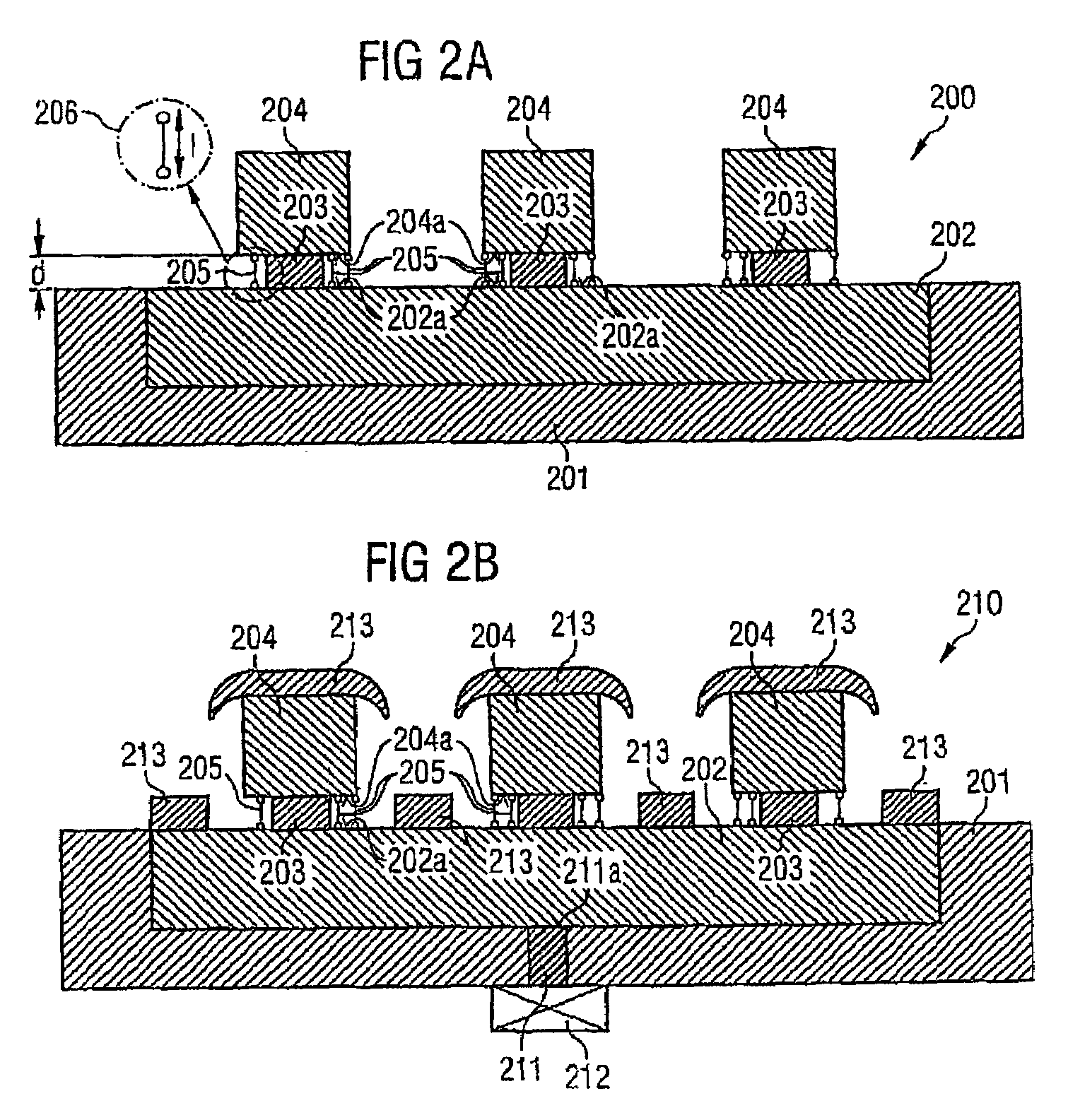
The invention relates to a molecular electronics arrangement comprising a substrate, at least one first strip conductor having a surface and being arranged in or on the substrate, a spacer which is arranged on the surface of the at least one first strip conductor and which partially covers the surface of the at least one first strip conductor, and at least one second strip conductor which is arranged on the spacer and comprises a surface which faces the surface of the at least one first strip conductor in a plane manner. The spacer partially covers the surface of the at least one second strip conductor, and defines a pre-determined distance between the at least one first strip conductor and the at least one second strip conductor. The inventive molecular electronics arrangement also comprises molecular electronics molecules which are arranged between a free region of the surface of the at least one first strip conductor and a free region of the surface of the at least one second strip conductor, the length of said molecules being essentially equal to the distance between the at least one first strip conductor and the at least one second strip conductor. The invention also relates to a method for producing a molecular electronics arrangement.

Description

CROSS-REFERENCE TO RELATED APPLICATIONS[0001]This application is a U.S. National-Stage entry under 35 U.S.C. § 371 based on International Application No. PCT / DE02 / 02379, filed 1 Jul. 2002, which was published under PCT Article 21 (2); this application also claims priority under 35 U.S.C. § 119 to German Application No. DE 101 32 640.8, filed Jul. 5, 2001.BACKGROUND OF THE INVENTION[0002]The invention relates to a molecular electronics arrangement and a method for fabricating a molecular electronics arrangement.[0003]Conventional silicon microelectronics will reach its limits as miniaturization advances further. In particular the development of increasingly smaller and more densely arranged transistors of hundreds of millions of transistors per chip will be subject to fundamental physical problems in the next ten years. If structural dimensions fall below 80 nanometers, the components are influenced by quantum effects in a disturbing manner, and they are dominated by quantum effects ...

Claims


Application Information

Patent Timeline
Patent Type & Authority Patents(United States)
IPC IPC(8): H01L35/24B82B1/00G11C11/21G11C13/02H10K99/00
CPCB82Y10/00G11C13/0014G11C13/0019H01L51/0595H01L51/005H01L51/0052H01L51/0093H01L51/0048H10K85/221H10K85/60H10K85/615H10K85/761H10K10/701
Inventor HARTWICH, JESSICAKRETZ, JOHANNESLUYKEN, RICHARD JOHANNESROSNER, WOLFGANG
Owner POLARIS INNOVATIONS
Learn More