
Apparatus for remotely imaging a region

a remote imaging and optical imaging technology, applied in the field of optical imaging systems, can solve the problems of consuming substantial power, affecting and the bulky nature of conventional crts, and achieve the effect of improving the coupling of reflected ligh

Inactive Publication Date: 2007-03-13
MICROVISION
View PDF25 Cites 86 Cited by
  • Summary
  • Abstract
  • Description
  • Claims
  • Application Information

AI Technical Summary

Benefits of technology

[0014]In another embodiment according to the invention, a separate fiber carries the illuminating light. To improve coupling of reflected light into the transmission fiber, the separate fiber and the transmission fiber are bonded together with their far or intermediate fields overlapped. Each of the transmission fiber and the separate fiber are formed as D-shaped fibers so that the cores of the fibers can be positioned substantially closely.

Problems solved by technology

Such devices suffer from several limitations.
Conventional CRTs are typically bulky and consume substantial amounts of power, making them undesirable for portable or head-mounted applications.
Such screens have limited use in head mounted applications or in applications where the display is intended to occupy only a small portion of a user's field of view.
For example, conversion between electrical signals and optical signals typically induces image distortion and noise.
Such systems can induce some form of color distortion.
However, such controllers and shielding can impose significant weight and size limitations.
In head-mounted applications, this additional weight can place stress on the wearer's neck and may also increase the difficulty of packaging.

Method used


Image

  • Apparatus for remotely imaging a region
  • Apparatus for remotely imaging a region
  • Apparatus for remotely imaging a region

Examples


Embodiment Construction

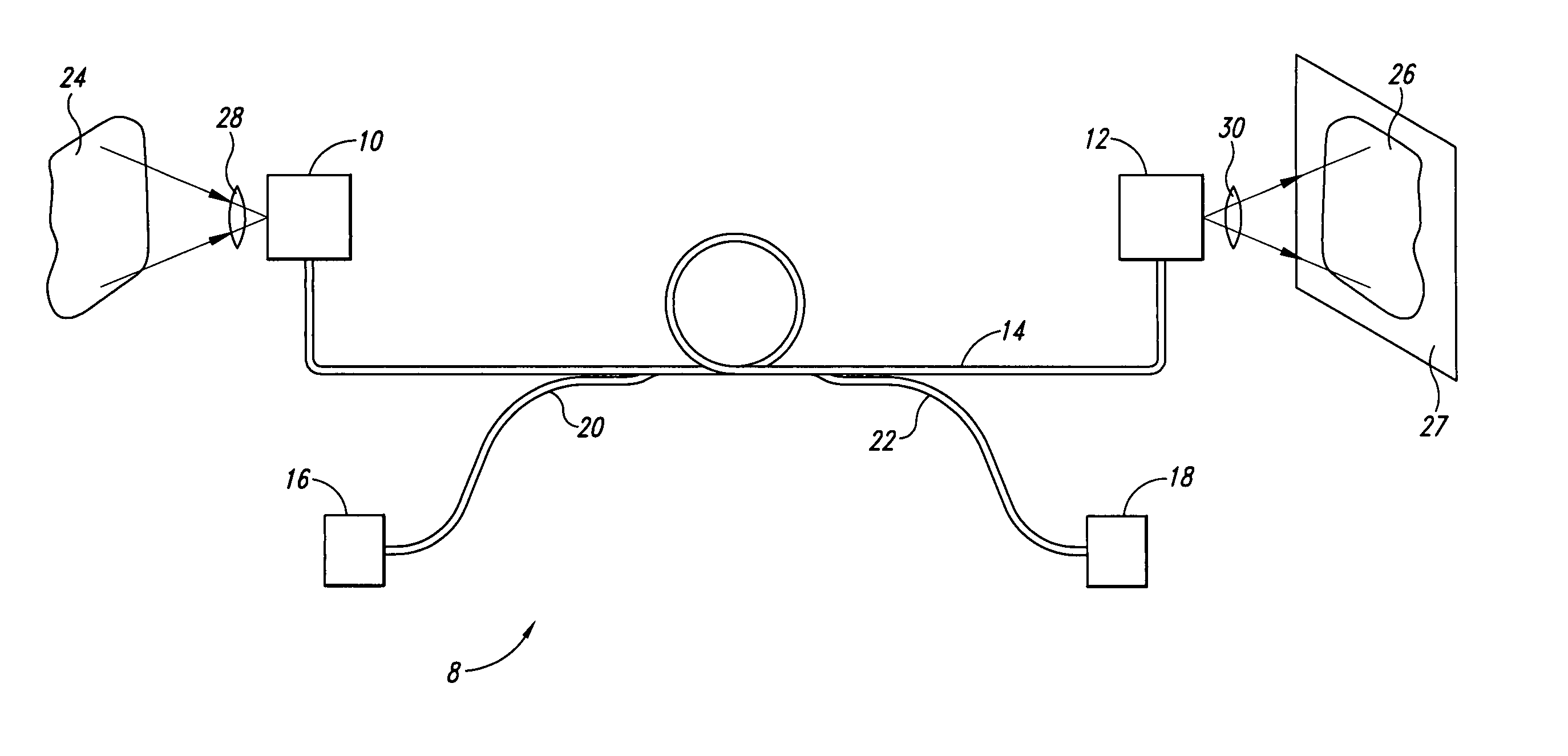
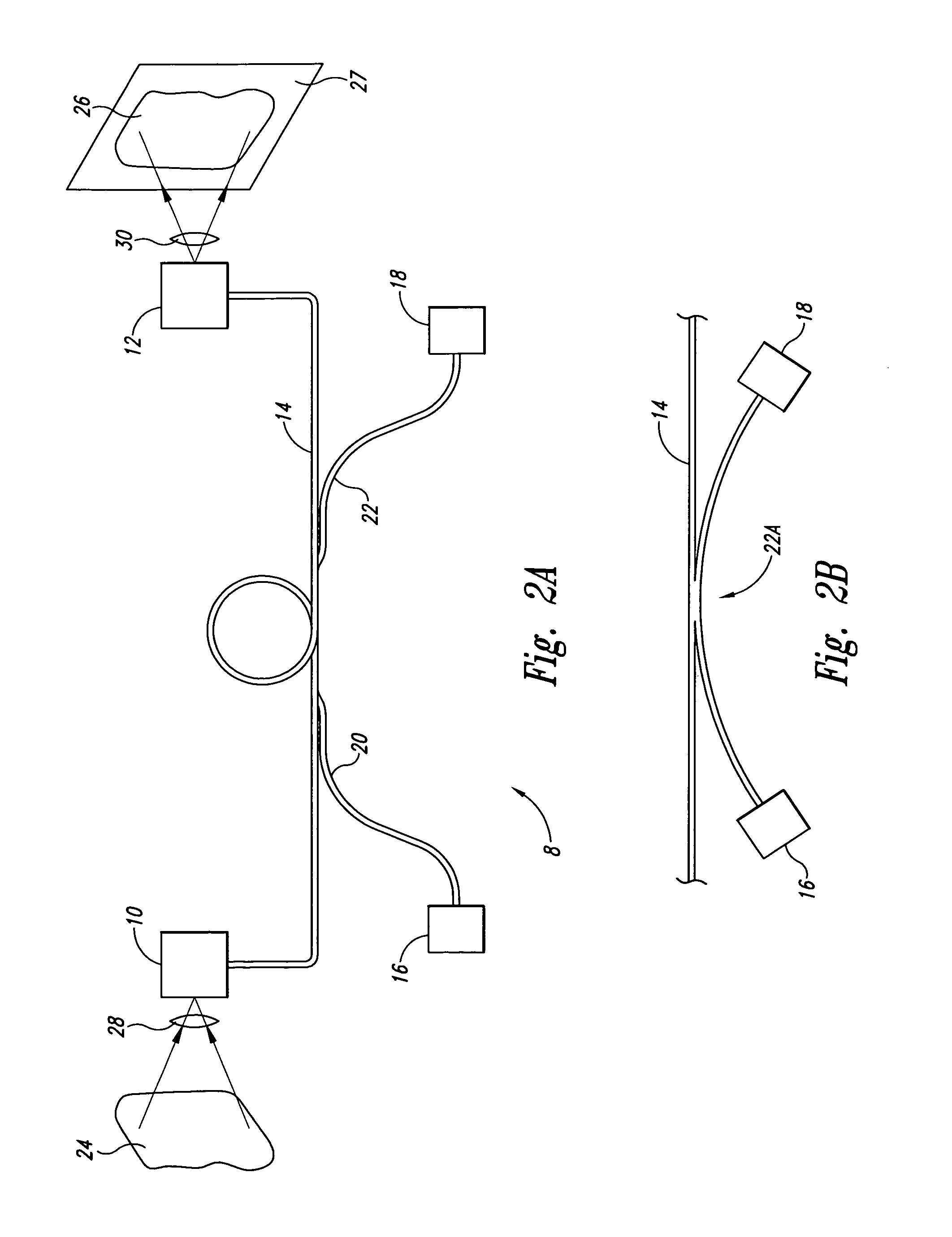
[0035]As shown in FIG. 2A, a dual-ended optical imager 8 is formed from a pair of scanners 10, 12 linked by a transmission fiber 14, where each of the scanners 10, 12 acts as an optical transceiver. The structure and operation of the scanners 10, 12 are described in greater detail herein with respect to FIGS. 5 and 6. Also, an example of a fiber-coupled scanning display is found in U.S. Pat. No. 5,596,339 of Furness et. al., entitled VIRTUAL RETINAL DISPLAY WITH FIBER OPTIC POINT SOURCE which is incorporated herein by reference. As will also be explained below, the scanners 10, 12 are synchronized so that they scan in substantially the same pattern at substantially the same rate.

[0036]A pair of light emitters 16, 18 are coupled to the transmission fiber 14 by respective fiber couplers 20, 22 to provide input light for illumination. As shown in FIG. 2B, a single fiber coupler 22A can couple light form both of the light emitters 16, 18 in the transmission fiber. Returning to FIG. 2A, ...


PUM


Abstract

A device for image transmission includes a first scanner at a first location and a second scanner at a second location, with an optical fiber linking the scanners. The first scanner scans the first location and couples light from the first location to the optical fiber. The fiber transmits the light to the second location where the second scanner constructs an image of the second location from the light. The two scanners are synchronized so that the constructed image corresponds directly to the scanned scene. The second scanner may be part of a retinal scanner, so that the image is formed directly on the user's retina. In another embodiment, the each of the scanners acts as a transceiver so that imaging is bi-directional.

Description

[0001]This application is a continuation of application Ser. No. 09 / 129,739, filed Aug. 5, 1998 now U.S. Pat. No. 6,583,772.TECHNICAL FIELD[0002]The present invention relates to optical imaging systems and, more particularly, to systems employing scanning inputs or outputs.BACKGROUND OF THE INVENTION[0003]A variety of techniques are available for providing visual displays of graphical or video images to a user. For example, cathode ray tube displays (“CRTs”), such as televisions and computer monitors, are very common. Such devices suffer from several limitations. Conventional CRTs are typically bulky and consume substantial amounts of power, making them undesirable for portable or head-mounted applications.[0004]Flat panel displays, such as liquid crystal displays, plasma displays, and field emission displays, may be less bulky and consume less power. However, typical flat panel displays utilize screens that are several inches across. Such screens have limited use in head mounted ap...

Claims


Application Information

Patent Timeline
IPC IPC(8): G09G5/00G02B26/08G02B26/10G02B27/01
CPCG02B27/017
Inventor LEWIS, JOHN R.TEGREENE, CLARENCE T.
Owner MICROVISION
Learn More