Radio frequency device

a radio frequency device and frequency technology, applied in the direction of electrical apparatus casings/cabinets/drawers, semiconductor/solid-state device details, wireless commuication services, etc., can solve the problem of degrading the characteristics of the radio frequency devi

Inactive Publication Date: 2007-03-13
COLLABO INNOVATIONS INC
View PDF28 Cites 7 Cited by
  • Summary
  • Abstract
  • Description
  • Claims
  • Application Information

AI Technical Summary

Benefits of technology

[0015]In view of these points, an object of the present invention is to provide a radio frequency device capable of being miniaturized without any degradation in radio frequency characteristics and capable of making excellent the junction between the metal shielding cap and the dielectric multilayer circuit board.

Problems solved by technology

This affects the radio frequency matching of the transistor, and degrades the characteristics of the radio frequency device.
Moreover, in a structure where the side walls of the metal shielding cap 1 and the ground patterns on the side surfaces of the dielectric multilayer circuit board 2 are soldered or welded to thereby join the metal shielding cap 1 and the dielectric multilayer circuit board 2 together, the following problem arises: When there is a deviation between the dimensions of the metal shielding cap 1 and the outer dimensions of the dielectric multilayer circuit board 2, the metal shielding cap 1 does not fit on the dielectric multilayer circuit board 2, or a float (gap) is caused at the junction between the metal shielding cap 1 and the dielectric multilayer circuit board 2 to cause a contact failure.

Method used


Image

  • Radio frequency device
  • Radio frequency device
  • Radio frequency device

Examples


first embodiment

[0045](First Embodiment)

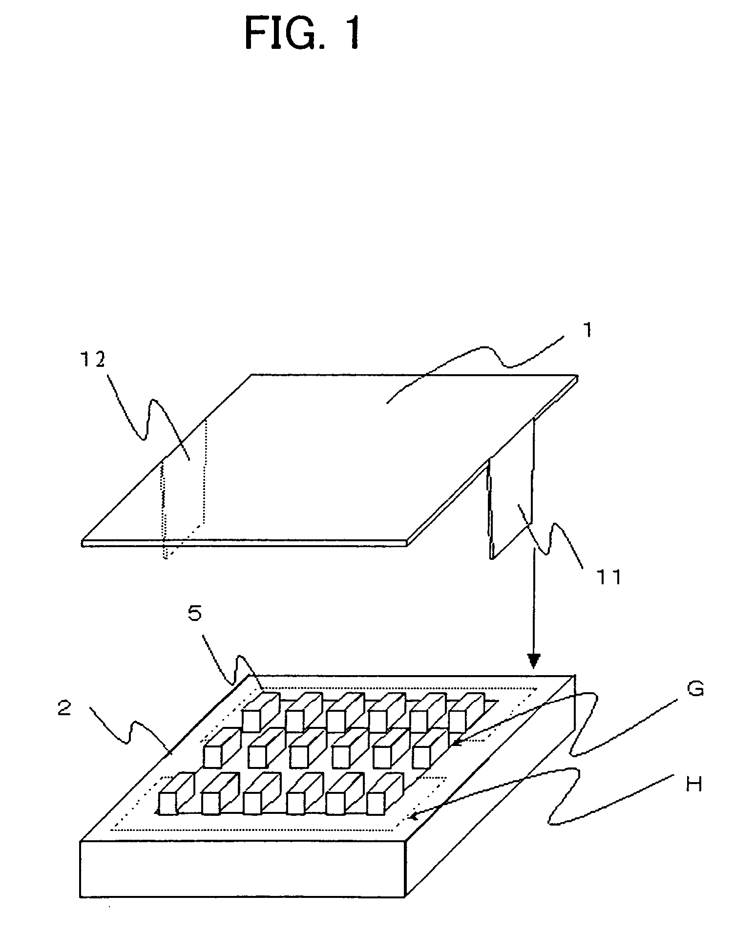
[0046]FIG. 1 shows an example of the structure of a radio frequency device according to a first embodiment of the present invention. As shown in FIG. 1, this radio frequency device comprises: a dielectric multilayer circuit board 2 being, for example, rectangle, being made of, for example, alumina and on the surfaces of which ground patterns (see FIG. 7) are formed; radio frequency circuit parts 5 and a transmission line (see FIG. 7) disposed on the top surface of the dielectric multilayer circuit board 2; and a metal shielding cap 1 made of, for example, nickel.

[0047]The metal shielding cap 1 is formed by bending, pressing or the like, and comprises, for example, a top plate 12 being, for example, rectangular and grounded side walls 11. The side surfaces are open except for the grounded side walls 11. The top plate 12 is disposed above the radio frequency circuit parts 5 and substantially parallel to the dielectric multilayer circuit board 2. The grounded si...

second embodiment

[0054](Second Embodiment)

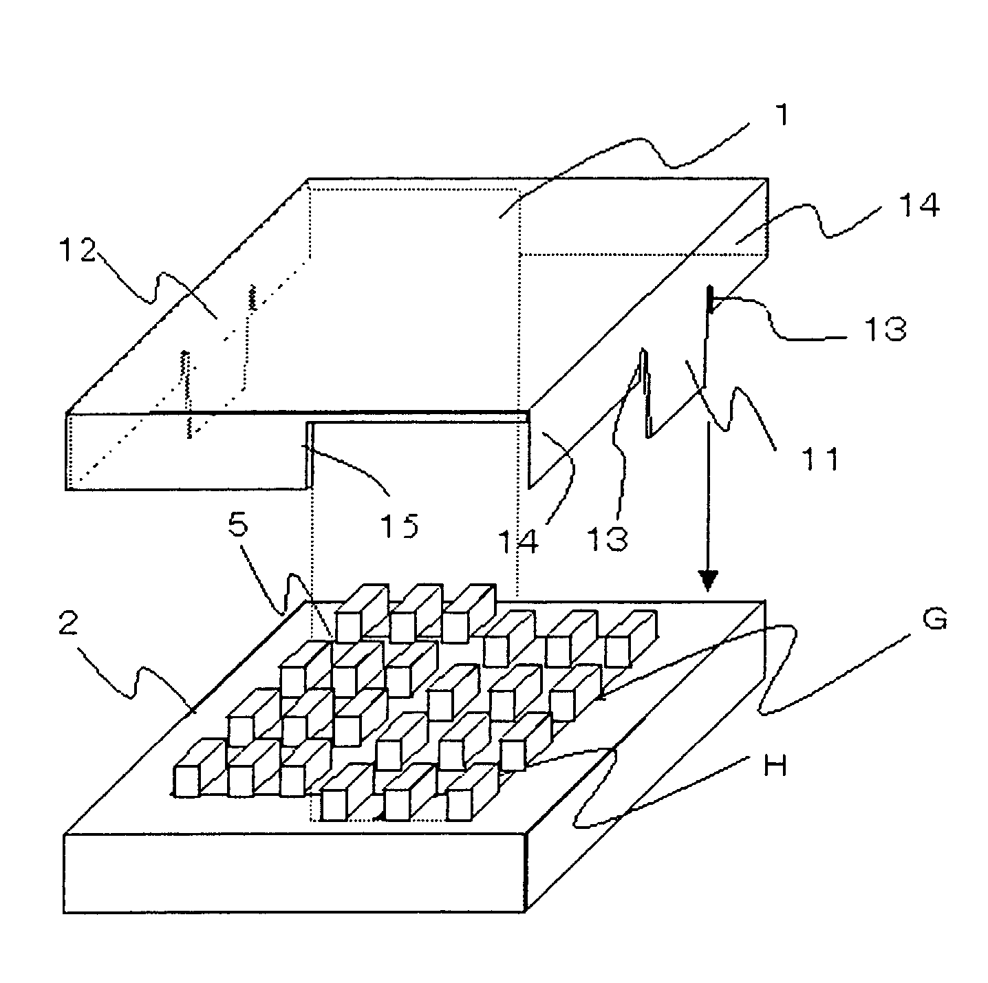
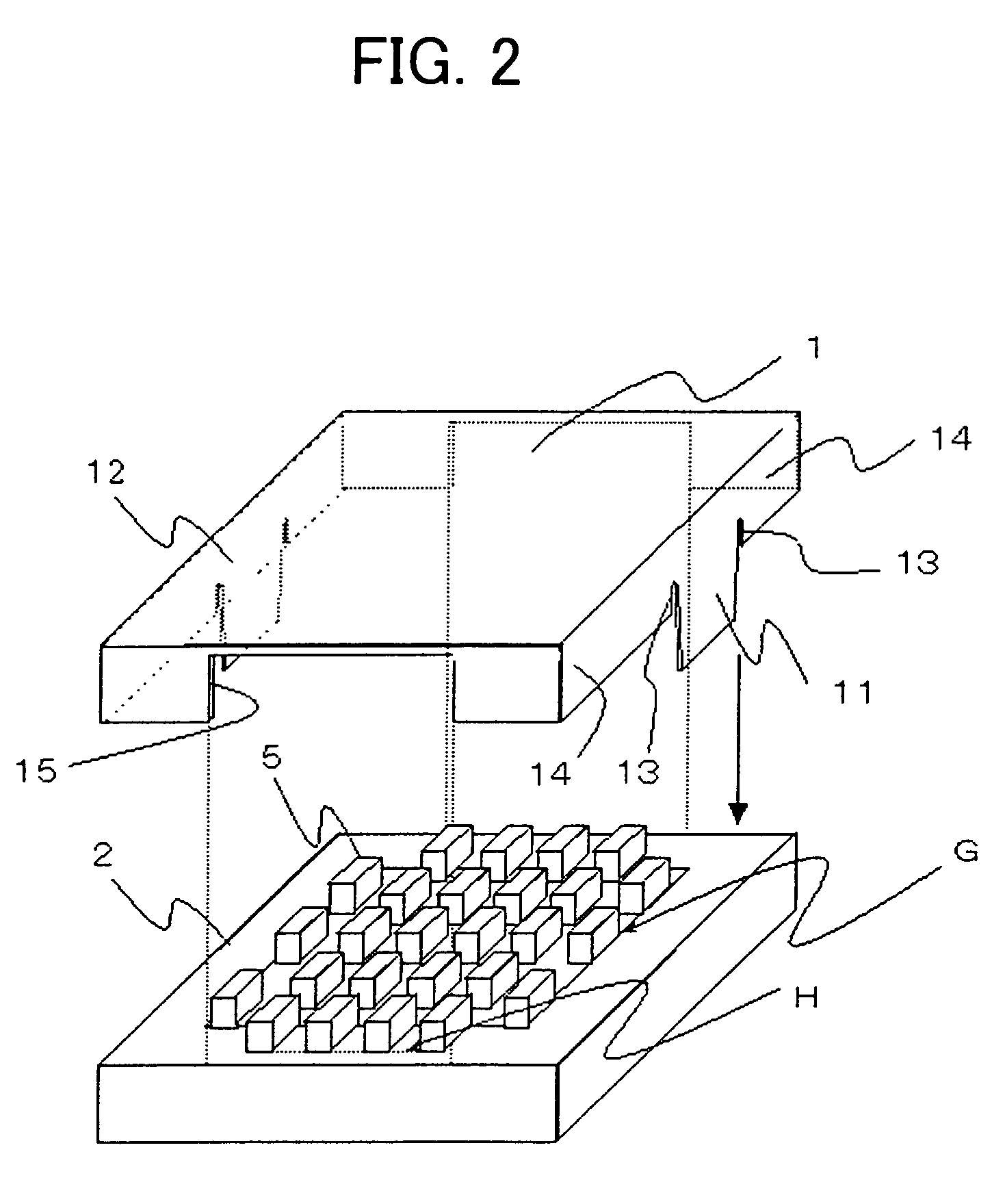
[0055]FIG. 2 shows an example of the structure of a radio frequency device according to a second embodiment of the present invention. As shown in FIG. 2, this radio frequency device comprises: a dielectric multilayer circuit board 2 being, for example, rectangle, being made of, for example, alumina and on the surfaces of which ground patterns (not shown) are formed; radio frequency circuit parts 5 and a transmission line (not shown) disposed on the top surface of the dielectric multilayer circuit board 2; and a metal shielding cap 1 made of, for example, nickel.

[0056]The metal shielding cap 1 is formed by bending or pressing, and comprises a top plate 12 being, for example, rectangular, grounded side walls 11 and non-grounded side walls 14. Notches 13 which are opened downward are provided at the boundary between the grounded side walls 11 and the non-grounded side walls 14, and the side surfaces are open except for the grounded side walls 11 and the non-gro...

third embodiment

[0066](Third Embodiment)

[0067]Next, a third embodiment of the present invention will be described.

[0068]According to the third embodiment of the present invention, in the radio frequency device shown in FIG. 2, radio frequency circuit parts 5 whose impedances are sensitively affected by the distance from the metal shielding cap 1 adjoining the non-grounded side walls 14 of the metal shielding cap 1, for example, chip coils are disposed in the parts of the non-grounded side walls 14 of the metal shielding cap 1 that are opened so that the radio frequency circuit parts 5 are not in contact.

[0069]FIG. 9 shows variations in the inductance value of a chip coil (chip inductor) as a radio frequency circuit part 5 when the metal shielding cap 1 is brought near to the chip coil. Although depending on the pattern structure and directivity of the chip coil, the inductance value of the chip coil when the metal shielding cap 1 comes to a position next to the chip coil at a distance of 0.80 to 0....


PUM


Abstract

In the present radio frequency device, a radio frequency circuit part and a transmission line are disposed on the top surface of a circuit board on the surface of which a ground pattern is provided, and a metal shielding cap is fixed to the circuit board so as to cover the radio frequency circuit part and the transmission path. The metal shielding cap includes: a top plate disposed above the radio frequency circuit part and substantially parallel to the circuit board; a grounded side wall being provided so as to hang down from a part of an edge of the top plate, having a spring property and being joined to the ground pattern of the circuit board, and a side wall is open except for the grounded side wall.

Description

BACKGROUND OF THE INVENTION[0001]1. Field of the Invention[0002]The present invention relates to a radio frequency device having a metal shielding cap structure.[0003]2. Description of the Prior Art[0004]In recent years, information communications have played an extremely important part, and demands for mobile communication systems have rapidly been increasing. Under such circumstances, for mobile telephones and cordless telephones, because of demands for system miniaturization, it is becoming extremely important to miniaturize devices constituting a radio frequency circuit block.[0005]Conventionally, as a radio frequency device which is one of the devices in a radio frequency circuit block of a portable telephone employing the PDC (personal digital cellular) system, in particular an amplifying device as a radio frequency amplifier for transmission, a gallium arsenide field effect transistor is used because of its excellent radio frequency characteristics.[0006]FIG. 7 shows an examp...

Claims


Application Information

Patent Timeline
Patent Type & Authority Patents(United States)
IPC IPC(8): H04M1/00H01L23/02H05K3/34H05K5/00H05K9/00
CPCH05K9/0039H05K5/0091H05K3/3405H01L2224/48091H01L2224/48227
Inventor YAMAMOTO, KOUKIYOSHIKAWA, NORIYUKIOHASHI, KAZUHIKO
Owner COLLABO INNOVATIONS INC
Why Eureka
Try Eureka